GF46.35-P-0001KA | Electric power steering (ES), function | 18.11.10 |
MODEL 169.0 /3, 245.2 as of model year 2009 /YoM 08 model refinement package
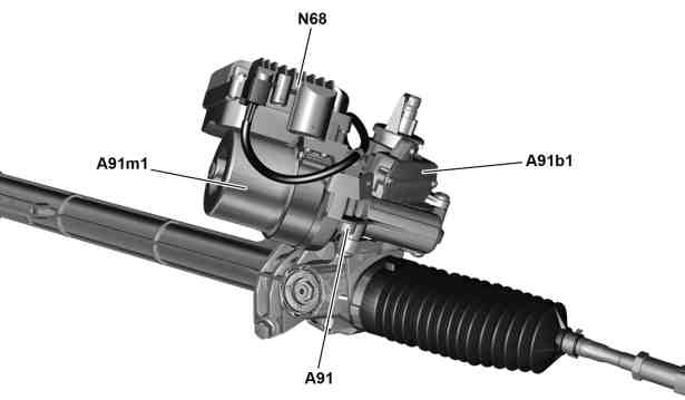
P46.35-2037-05
A91 Electromechanical control unit (ES)
A91b1 Electrical power steering (ES) torque sensor
A91m1 Electrical power steering (ES) actuator motor
N68 Electrical power steering (ES) control unit
Function requirements, general
Circuit 15 ON and engine rpm > 500 rpm (except with electric drive, model 169.090)
Circuit 15 ON (on model 169.090)
The status of circuit 15 is sent by the EZS control unit (N73) via the engine compartment CAN (CAN C) to the electrical power steering (ES) control unit.
The engine rpm is sent to the electrical power steering (ES) control unit by the ME-SFI control unit (N3/10) (with gasoline engine) or CDI control unit (N3/9) (with diesel engine) via the engine compartment CAN.
Electric power steering, general
The electric power steering system consists of the rack and pinion steering gear, the electrical power steering (ES) control unit and the electromechanical controller unit (ES), which comprises the electric power steering (ES) actuator motor and the electrical power steering (ES) torque sensor.
-----------------------------------------------------------------------------------------
The electric power steering system performs stepless, speed-dependent regulation of the power steering.
The advantages compared to hydraulic power steering are:
- Improved steering feel
- Fuel saving
- No steering oil required
- Compact design
- Speed-dependent power assistance
- Steering return is assisted
- Diagnosis capability
The electric power steering function comprises the following subfunctions:
Power steering function sequence
Steering assistance function sequence
Limp-home mode function sequence
Function sequence for display in instrument cluster (A1)
-----------------------------------------------------------------------------------------
Power steering function sequence
The electrical power steering (ES) control unit requires the following information to calculate the steering power assistance required:
- Current steering moment, from electrical power steering (ES) torque sensor
- Current wheel speeds, detected by
- left front rpm sensor (L6/1)
- right front rpm sensor (L6/2)
- left rear rpm sensor (L6/3)
- right rear rpm sensor (L6/4)
from ESP and BAS control unit (N47-5) via engine compartment CAN
- Steering angle and steering speed from steering angle sensor (N49) in steering column tube module (N80) via engine compartment CAN
- Current rpm of combustion engine via engine compartment CAN (except model 169.090)
- Status of electric drive via engine compartment CAN (on model 169.090)
-----------------------------------------------------------------------------------------
- Current rotor position of electric power steering (ES) actuator motor from motor position sensor in electromechanical controller unit (ES)
The electric power steering (ES) control unit uses this information to calculate the steering force assistance to be applied from the stored characteristics map and actuates the electric power steering (ES) actuator motor accordingly.
The electric power steering (ES) actuator motor supports the driver's steering torque via a worm gear at the drive pinion of the rack-and-pinion steering.
The direction of rotation of the electric power steering (ES) actuator motor depends on the direction of movement of the steering wheel.
The servo assistance is slowly shut down with circuit 15 OFF.
-----------------------------------------------------------------------------------------
Steering assistance function sequence
The steering assistance function is intended to help the driver achieve the optimal steering characteristics in critical situations. The steering assist function is implemented with the aid of the electrical power steering (ES) control unit and by means of the ESP and BAS control unit.
The following functions are performed here:
- Driver support or stabilization through countersteering of a vehicle with oversteer
- Driver support when braking on different road surfaces
The current vehicle status is detected by the ESP and BAS control unit. If necessary, the ESP and BAS control unit forwards the message "Steering assistance torque request" via the engine compartment CAN to the electrical power steering (ES) control unit, which actuates the electric power steering (ES) actuator motor accordingly.
-----------------------------------------------------------------------------------------
Limp-home mode function sequence
When the electric power steering is switched on (via circuit 15 ON), the electrical power steering (ES) control unit performs a self-test. If a fault is detected the servo assist is not switched on.
The vehicle can be steered with increased force of the hand.
When the vehicle is in operation, the electrical power steering (ES) control unit checks the signals from the electrical power steering (ES) torque sensor, the rotor position sensor and the current sensors of the electric power steering (ES) actuator motor. If these signals are outside the defined upper and lower limits, the electrical power steering is immediately switched off by the electrical power steering (ES) control unit.
The vehicle can be steered with increased force of the hand.
-----------------------------------------------------------------------------------------
Display on instrument cluster function sequence
The electrical power steering (ES) control unit sends the request for a warning message via the engine compartment CAN to the instrument cluster.
The multifunction display (A1p13) of the instrument cluster then shows the warning message "Power steering defective! Visit workshop!".
| Electrical function schematic for electric power steering | Model 169 | |
Model 245 | |||
Electric power steering (ES), location of components | |||
Electric power steering (ES), block diagram | |||
Component description for instrument cluster | A1 | ||
Component description for CDI control unit | N3/9 With engine 640 | ||
Component description for ME-SFI [ME] control unit | N3/10 With engine 266 | ||
Energy monitoring control unit, component description | N3/27 With engine 780.992 in model 169.090 | ||
ESP/BAS control unit/component description | N47-5 | ||
Electrical power steering control unit (ES), component description | N68 | ||
EZS control unit, component description | N73 | ||
Component description for steering column tube module | N80 |
Referenced documents
- gf0716p6000od Component description for CDI control unit
- gf0761p6000md Component description for ME-SFI [ME] control unit
- gf0820p3000ke Component description for energy monitoring control unit
- gf4245p4502ka ESP/BAS control unit/component description
- gf4635p000102ka Electric power steering (ES), location of components
- gf4635p000103ka Electric power steering (ES), block diagram
- gf4635p7010ka Electrical power steering control unit (ES), component description
- gf5421p6050ka Steering column module, component description
- gf5430p6000ka Component description for instrument cluster
- gf8057p6003ka EZS control unit, component description
- pe4635p205097bab Electrical function schematic for electric power steering
- pe4635p205097qb Electrical function schematic for electric power steering