
Shown on engine 272.964 |
1 | Intermediate flange |
2 | Guide pulley |
3 | Coolant hose |
5 | Segment disc |
6 | Central valves |
7 | Timing case cover |
8 | Power steering pump |
9 | Crankshaft radial sealing ring |
12 | Bolts |
13 | Screw |
A9 | Refrigerant compressor |
P01.40-2260-06

MODEL 219.357 |
16 | Coolant lines |
16a | Electrical connector |
16b | Bolts |
17 | Bracket |
17a | Bolts |
Y125 | Low temperature cooling system shutoff valve |
P07.16-3104-06
| Remove/install | ||
Warning | Risk of injury caused by fingers being jammed or pinched when removing, installing or aligning hoods, doors, trunk lid/rear-end door or sliding roof. | No parts of the body or limbs should be within the operating area when the components are moving. | |
Danger | Risk of death caused by vehicle slipping or toppling off of the lifting platform. | Align vehicle between vehicle lift columns and position the four support plates at the vehicle lift support points specified by the vehicle manufacturer. | |
Topical note | Information on preventing damage to electronic components due to electrostatic discharge | ||
1 | Turn key in ignition lock to position "0" | Model 211, 219 with engine 272, 273 | |
2 | Remove air filter housing with engine air intake ducts | ||
3 | Remove lower engine compartment paneling |
| |
Model 219 with engine 272, 273 | |||
4 | Drain engine oil | ||
| Model 211, 219 with engine 272 | ||
| Model 211, 219 with engine 273 | ||
Warning | Risk of injury to skin and eyes suffering scalding from contact with hot coolantspray. Risk of poisoning from swallowing coolant. | Do not open cooling system unless coolant temperature is below 90 °C. Open cap slowly and release the pressure. Do not pour coolant into beverage containers. | |
5 | Drain coolant at radiator | ||
Topical note | Notes on coolant | ||
6 | Disconnect coolant hose on coolant temperature regulator housing | ||
7 | Disconnect coolant hose (3) at coolant pump | ||
8 | Remove fan shroud | ||
9 | Attach guard plate for radiator/condenser | ||
| |||
10 | Remove poly-V belt, tensioning device and guide pulley (2) | ||
11.1 | Remove air pump | Model 211 (except 211.057/257), 219 (except 219.357) with engine 272, 273 | |
11.2 | Open hose clamps using hose clamp pliers and detach coolant lines (16) | Model 211.057/257, 219.357 | |
Hose clamp pliers | |||
12 | Remove coolant temperature control housing | ||
Installation: Replace O-ring and seal. | |||
13 | Remove oil filter housing with oil-water heat exchanger | ||
14 | Remove power steering expansion reservoir |
| |
Model 219 with engine 272, 273 | |||
15.1 | Remove left and right air shutoff valve | Model 211 (except 211.057/257), 219 (except 219.357) with engine 272, 273 | |
15.2 | Disconnect electrical connection (16a), remove screw/bolts (16b) and low-temperature cooling system shutoff valve (Y125) | Model 211.057/257, 219.357 | |
Screw/bolt, shutoff valve bracket to cylinder head | |||
16.1 | Remove intermediate flange (1) of air shutoff valve | Model 211 (except 211.057/257), 219 (except 219.357) with engine 272, 273 | |
Screw/bolt, left air shutoff valve intermediate flange to cylinder head | |||
16.2 | Remove screw/bolts (17a) and bracket (17) | Model 211.057/257, 219.357 | |
Screw/bolt, low temperature circuit coolant line bracket to cylinder head or cylinder head front cover | |||
17 | Rotate engine at crankshaft center bolt in direction of engine rotation to a 40° crankshaft angle after top dead center (ignition TDC) | Socket wrench bit | |
18 | Install retaining lock for crankshaft/starter ring gear | ||
19 | Remove belt pulley/vibration damper | ||
20 | Remove front cover at left cylinder head | ||
Installation: After installing the front cover, check that the camshafts are positioned at a 55° crank angle BTDC. | |||
Refer to: | |||
| |||
Check basic position of camshafts | |||
21 | Remove front cover at the right cylinder head | ||
Installation: After installing the front cover, check that the camshafts are positioned at a 55° crank angle BTDC. | |||
Refer to: | |||
| |||
Check basic position of camshafts | |||
22 | Remove chain tensioner |
| |
Model 211, 219 with engine 272, 273Chain tensioner with thread M221.5 | |||
Installation: | |||
Model 211, 219 with engine 272 | |||
Model 211, 219 with engine 273 | |||
23 | Remove camshaft adjuster for exhaust camshafts | ||
24 | Remove camshaft adjuster for intake camshafts | ||
25 | Remove alternator | ||
26 | Remove the oil dipstick guide tube |
| |
Model 211 with engine 272, 273with front sump | |||
27 | Remove power steering pump (8) |
| |
Model 219 with engine 272, 273 | |||
Detach power steering pump (8) with expansion reservoir from front cover or from timing case cover (7) and place to one side with their connected lines. | |||
28 | Detach refrigerant compressor (A9) and put it on the side with connected lines | Screw/bolt, refrigerant compressor to timing case/crankcase/engine support | |
29 | Remove oil pan |
| |
Model 211.087/090/092/287/290/292with front sump | |||
If the oil pan cannot be released from the cylinder crankcase, warm oil pan in area of sealing surface with a hot air gun, then push assembly wedge between sealing surface to separate oil pan from the cylinder crankcase. | |||
30 | Remove bolts/screws (12, 13) | Screw/bolt, cylinder head to timing case | |
31 | Detach timing case cover (7) | ||
Notes on sealant path for timing case cover | |||
Installation: Replace crankshaft radial sealing ring (9). Replace both sealing rings in timing case cover (7) and apply sealant to sealing surface of the timing case cover (7). | |||
Installation: Pay attention to different lengths and diameters of screw/bolts: | |||
| |||
Bolt plan for timing case cover | |||
Engine 272 in model 211, 219Screw/bolt, timing case cover to cylinder crankcase | |||
Engine 273 in model 211, 219Bolt, timing case cover to cylinder crankcase | |||
Sealant, Loctite 5970, 50 ml | |||
Application gun | |||
| Clean | ||
32 | Clean oil pan sealing surfaces, oil pan bottom section and timing case cover (7) | ||
| |||
Loctite 7200 | |||
Loctite 7063 (400 ml) cleaning spray | |||
33 | Install in the reverse order | ||
34 | Check engine oil level; correct if necessary | ||
| Model 211, 219 with engine 272 | ||
| Model 211, 219 with engine 273 | ||
Warning | Risk of accident from vehicle starting off by itself when engine running. Risk of injury (bruises and burns) resulting from working on the engine while it is being started or when it is running. | Secure vehicle to prevent it from starting off by itself. Wear closed and snug-fitting work clothes. Do not touch hot or rotating parts. | |
35 | Carry out an engine test run and check engine for leak tightness | ||
36 | Check cooling system for leaktightness |

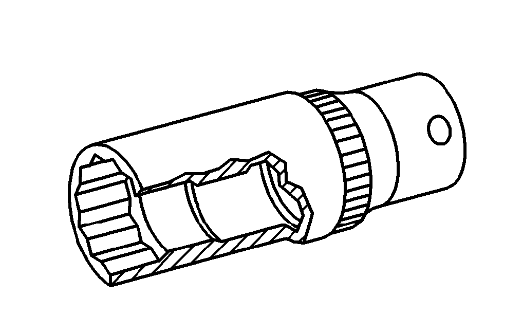

003 589 03 37 00
Hose clamp pliers
001 589 65 09 00
Socket wrench bit
112 589 00 25 00
Application gun
Henviste dokumenter
- ah0140p100001va Oplysninger om tætningsmiddelforløb takthusdæksel
- ah2000n208001a Oplysninger om kølervæske
- ah5400p000101a Oplysninger med henblik på at undgå skader på elektroniske komponenter på grund af elektrostatisk afladning
- ap1800p0101pit Motorolie- og oliefilterskift
- ap1800p0101sx Motorolie- og oliefilterskift
- ap1800p0101sxi Motorolie- og oliefilterskift
- ar0100p005001a
- ar0130p5700ts
- ar0130p5700tt
- ar0140p800001va
- ar0145p7500ts
- ar0145p7500ts
- ar0145p7500tw
- ar0145p7500tw
- ar0330p1600ts
- ar0330p5000ts
- ar0510p7800ts
- ar0510p7800vb
- ar0520p6010ts
- ar0520p7201ts
- ar0520p7201tt
- ar0910p1150ts
- ar1320p0001ts
- ar1430p7200ts Af-, påmontering af luftfrakoblingsventil
- ar1430p7251ts Af- påmontering af luftpumpe
- ar1540p5032ts Af-, påmontering af generator
- ar1820p3471ts
- ar1840p3510ts
- ar1840p3510tw
- ar2000p1010ts
- ar2000p1142ts
- ar2010p2460ts
- ar2040p6800ts
- ar4625p1000ts Af- og påmontering af ekspansionsbeholder
- ar4625p1000tx Af- og påmontering af ekspansionsbeholder
- ar4630p0500ts Af- påmontering af servopumpe
- ar4630p0500tx Af- påmontering af servopumpe
- ar6120p1105t
- ar6120p1105tx
- as0000z000501a Fare for ulykke ved automatisk igangsætning når motoren kører. Fare for personskade på grund af knusning og forbrænding, hvis der arbejdes mens motoren startes eller kører
- as0000z001001a Livsfare, hvis køretøjet glider ned fra eller tipper på liften.
- as0000z001101a Fare for personskade pga. fastklemning eller knusning af fingre ved af-, påmontering og indstillingsarbejde på motorhjelm og bagklap, døre, dæksler og soltag.
- as2000z000101a Risiko for skoldningsskader på hud og øjne pga. sprøjtende, varm kølervæske. Risiko for forgiftning ved indtagelse af kølervæske
- wf5850p011001a