
P01.30-2202-09
1 Intermediate flange
2 Catalytic converter
3 Coolant hose
6 Cylinder head gasket
8 Coolant temperature sensor connector
4 Coolant connection
5 Cylinder head
Modification notes
8.2.11 | Value changed: screw/Only pour fuels into suitable and appropriately marked containers cylinder head to timing case | ||
Value changed: Screw/bolt, catalytic converter to exhaust manifold |
| Remove/install | ||
Danger! | Risk of death caused by vehicle slipping or toppling off of the lifting platform. | Align vehicle between columns of vehicle lift and position four support plates at vehicle lift support points specified by vehicle manufacturer. | |
Danger! | Risk of explosion caused by fuel igniting, risk of poisoning caused by inhaling and swallowing fuel and risk of injury to eyes and skin caused by contact with fuel | No fire, sparks, open flames or smoking. Wear protective clothing when handling fuel. | |
| Information on preventing damage to electronic components due to electrostatic discharge | ||
1 | Open engine hood | ||
Danger! | Risk of explosion caused by escaping oxyhydrogen gas. Risk of injury caused by caustic burns to eyes, skin and mucous membranes from battery electrolyte (contains diluted sulfuric acid) or metal spatter due to short circuit. Risk of burn injuries caused by short circuit. Risk of poisoning caused by swallowing battery electrolyte (contains diluted sulfuric acid) or absorption of lead over the skin or orifices | No fire, sparks, open flames or smoking. Wear acid-resistant gloves and clothing and safety glasses with side guards. Do not place any conductive objects on the battery and avoid any short circuit from battery positive to ground. Only pour liquid battery electrolyte (diluted sulfuric acid) into suitable and appropriately marked containers. | |
2 | Disconnect ground line from battery | ||
| Notes on battery | ||
3 | Raise vehicle | ||
4 | Remove bottom engine compartment paneling | Installation: Install bottom engine compartment paneling only after engine test run. | |
Danger! | Risk of injury to skin and eyes caused by scalding from contact with hot coolant spray. Risk of poisoning caused by swallowing coolant. | Do not open cooling system unless coolant temperature is below 90°C. Open cap slowly and release the pressure. Do not pour coolant into beverage containers. Wear protective gloves, protective clothing and safety glasses. | |
5 | Drain coolant at radiator and at crankcase | ||
6 | Detach left catalytic converter (2) at exhaust manifold | | |
7 | Lower vehicle | ||
8 | Remove air filter housing | ||
9 | Remove ME-SFI [ME] control unit | ||
10 | Remove fan shroud | ||
11 | Attach guard plate for radiator/condenser | ||
| Guard plate for radiator/condenser | ||
12 | Remove poly-V belt | ||
13 | Remove poly-V belt tensioning device | ||
14 | Remove oil filter housing with oil-water heat exchanger | ||
15 | Remove power steering expansion reservoir | ||
16 | Remove front cover on left cylinder | Installation: After installing the front cover the position of the camshafts should be checked at 55° crank angle before top dead center (TDC): | |
Check basic position of camshafts. | |||
| |||
17 | Remove ignition coils at left cylinder | ||
18 | Remove oil separator | ||
19 | Remove left cylinder head cover | ||
20 | Remove resonance intake manifold | ||
21 | Remove alternator | ||
22 | Crank engine at center bolt for crankshaft to a 40° crank angle ATDC | Observe position of camshafts: | |
Check basic position of camshafts. | |||
| |||
23 | Remove chain tensioner | M241.5 | |
M221.5 | |||
Installation: Install new chain tensioner with thread of M221.5. The previously installed chain tensioner must not be reinstalled because during removal, its pressure pin is pressed into the end position. The thrust pin latch prevents this return stroke. This would overstretch the timing chain on reinstalling. | |||
24 | Remove camshaft adjuster for left cylinder head (5) | ||
25 | Remove aspirator shutoff valve at left cylinder head (5) | ||
26 | Remove intermediate flange (1) of air shutoff valve | | |
27 | Detach coolant hose (3) from coolant connection (4) on the back of the left-hand cylinder head (5) | The new cylinder head (5) is delivered without a coolant connection (4). | |
28 | Pull off plug (8) from coolant temperature sensor on the back of the left-hand cylinder head (5) | ||
29 | Pull out guide pin of slide rail on left-hand cylinder head (5) | ||
| |||
| |||
Installation: Apply sealant to slide rail pins before inserting them. | |||
| |||
Loctite 5970 sealant | |||
30 | Loosen cylinder head bolts in stages and remove them | To avoid stresses in cylinder head (5), cylinder head bolts must be loosened in the reverse order of the tightening instructions when the engine has cooled off: | |
Tightening specifications for cylinder head bolts | |||
| |||
| |||
31 | Remove left-hand cylinder head (5) from cylinder crankcase | Installation: Lay new cylinder head gasket (6) onto crankcase. Pay attention to fitted sleeves for fixing cylinder head (5). | |
| Information on applying sealant to cylinder head gasket | ||
32 | Check cylinder head bolts and replace if required | ||
| Clean | ||
33 | Clean sealing surfaces on left-hand cylinder head (5), cylinder crankcase and timing case cover | Do not use any sharp-edged tools or abrasive paper. The sealing surfaces will be damaged otherwise. | |
Blow out tapped holes for cylinder head bolts in crankcase with compressed air, and clean off any engine oil and coolant. | |||
Loctite 7200 | |||
Loctite 7063 cleaning spray (150 ml) | |||
34 | Check sealing surfaces on left cylinder head (5), cylinder crankcase and timing case cover for cracks and unevenness | The cylinder head (5) and cylinder crankcase must not be post-worked (surface grinding). The permissible manufacturing tolerances may be exceeded otherwise. For a complaint about the cylinder head (5), replace the timing case cover or cylinder crankcase. | |
Any distortion of the cylinder head (5) occurring in a longitudinal or transverse direction will be compensated for again during reassembly by tightening the cylinder head bolts. | |||
35 | Install in the reverse order | ||
36 | Change engine oil and oil filter element | ||
| Engine - oil and filter change | ||
| Checking | ||
Danger! | Risk of accident caused by vehicle starting off by itself when engine is running. Risk of injury caused by contusions and burns during starting procedure or when working near the engine as it is running | Secure vehicle to prevent it from moving by itself. | |
37 | Carry out an engine test run, and inspect engine and fuel system for leaks | ||
38 | Inspect cooling system for leaks |
Cylinder head/cylinder head bolts
Number | Designation | Engine | ||
BE01.30-P-1001-04B | Cylinder head bolt | Thread diameter | M | 11 |
Length (L) when new | mm | 170 | ||
Length (L) | mm | 172 | ||
See picture | - | |||
Exhaust system
Number | Designation | Engine | ||
BA49.10-P-1001-01N | Screw, catalytic converter to exhaust manifold | Nm | 20 | |
Air shutoff valve
Number | Designation | Engine | |
BA14.30-P-1004-02A | Screw/bolt, LH air shutoff valve intermediate flange to cylinder head | Nm | 14 |
Cylinder head
Number | Designation | Engine | |||
BA01.30-P-1003-01O | Cylinder head bolt on timing case | M8 | Nm | 20 | |
BA01.30-P-1016-01O | Bolt, cylinder head to crankcase | M11 | Stage 1 | Nm | 20 |
Stage 2 | Nm | 50 | |||
Stage 3 | ° | 90 | |||
Stage 4 | ° | 90 | |||

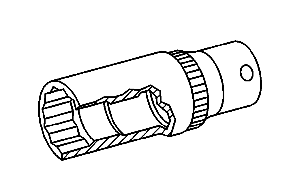


116 589 20 33 00
Threaded stud
Impact extractor
Wrench socket
Squeeze gun
001 589 65 09 00
116 589 01 34 00
112 589 00 25 00
Repair materials
Number | Designation | Order number |
BR00.45-Z-1013-01A | Loctite 5970 sealant | A 003 989 98 20 |
BR00.45-Z-1038-04A | Loctite 7200 | Henkel Loctite Deutschland GmbH |
BR00.45-Z-1046-04A | Loctite 7063 cleaning spray (150 ml) | A 001 986 71 71 10 |
참조 문서
- ah0130p100004rx 실린더 헤드 실링에 실링제 바르기 관련 지침
- ah5400p000101a 정전기 방전으로 인한 전자 부품 손상 방지 지침
- ah5410p000101a 배터리 관련 지침
- ah5410p000101a
- ap1800p0101va 엔진 오일 교환 및 오일 필터 교체
- ar0060p1000v 차량 들어 올리기, 정비대 위에 놓기
- ar0100p005001a 실런트를 제거하십시오.
- ar0120p5014va
- ar0120p5014va
- ar0120p9750va
- ar0130p5700vb
- ar0130p580003va 실린더 헤드 나사의 점검
- ar0130p580004v 실린더 헤드의 가이딩 블레이드 나사를 제거하십시오.
- ar0130p580007va 실린더 헤드 나사의 조임 지침
- ar0510p7800va
- ar0510p7800vb 체인 텐셔너 탈, 장착
- ar0520p601001vb 캠 샤프트의 기본위치를 점검하십시오.
- ar0520p6010va
- ar0520p7201va
- ar0708p7008va
- ar0910p1150va
- ar0920p1961va
- ar1322p1202va
- ar1325p3200va
- ar1430p7200vb
- ar1512p2003va
- ar1512p2003va
- ar1540p5032va
- ar1820p3471va
- ar2000p1010v
- ar2000p1142va
- ar2040p6800va
- ar4625p1000va
- ar5410p0003v
- ar6120p1105v
- ar8840p1000v 엔진 후드 열기, 수직으로 세우고, 닫기
- as0000z000501a 엔진이 작동 중인 상태에서 급발진에 의한 사고 위험 시동 또는 구동 중인 엔진 근처에서 작업할 때 차량에 부딪히거나 열에 의한 상해 위험
- as0000z001001a 리프터에서 차량이 미끄러지거나 틸팅 시 생명의 위험
- as2000z000101a 뜨거운 냉각수 분출 시 입은 화상에 의한 피부와 안구의 상해 위험 냉각수의 음용으로 인한 중독 위험
- as4700z000101a 인화에 의한 폭발 위험, 연료의 흡입 및 음용에 의한 중독 위험, 연료의 피부 및 안구 접촉에 의한 상해 위험
- as5410z000101a 단락 및 폭발성 기체 유출로 인한 화재/폭발 위험 배터리 전해액/증기, 단락 및 전기 아크에 노출 시 눈, 피부, 점막의 부식으로 인한 화상/상 해 위험 배터리 전해액을 삼키거나 피부
- wf5850p011001a