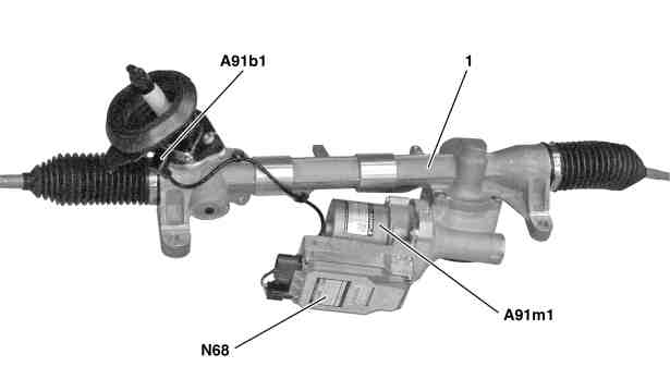
View of steering |
A91b1 | Electric power steering torque sensor |
A91m1 | Electric power steering actuator motor |
N68 | Electrical power steering control unit |
P46.35-2067-05
Location
The electrical power steering control unit is attached to the electric power steering actuator motor.
On vehicles up to model year 2016 and irrespective of the equipment specification, only one chassis CAN is available.
On vehicles as of model year 2016 two chassis CAN variants are available, depending on the equipment specification involved.
Variant 1
If the vehicle does not have any of the equipment codes quoted in variant 2, then as with model year 2016 only one chassis CAN (CAN E) is available.
Variant 2
If the vehicle has one of the following equipment codes, then two chassis CANs (chassis CAN 1 (CAN E1), chassis CAN 2 (CAN E2)) are available:
CODE 218 (Backup camera)
CODE 234 (Blind Spot Assist)
CODE 459 (Steel suspension with adjustable damping)
CODE 475 (Tire pressure monitor)
CODE 476 (Lane Keeping Assist)
CODE 513 (Speed Limit Assist)
CODE 614 (bi-xenon headlamp unit)
CODE 615 (Bi-xenon headlamps with active curve lights)
CODE 618 (Bi-xenon headlamps)
CODE 621 (Intelligent Light System (left-hand traffic))
CODE 622 (Intelligent Light System)
CODE 631 (Static LED headlamps for left-hand traffic system)
CODE 632 (Static LED headlamps for right-hand traffic system)
Tasks
The electrical power steering control unit has the following tasks:
Reading in of signals
Evaluation of input factors
Actuation of components
Transmission of requests/information
Reading in of signals
The input factors are read in over the following connections:
Direct line
Chassis CAN (Variant 1)
Chassis CAN 2 (Variant 2)
Direct line
The signals from the following component are read in via a direct line:
Electric power steering torque sensor
Chassis CAN (Variant 1)
The following signals are read in over the chassis CAN:
Steering assistance torque request and wheel speeds, from the Electronic Stability Program control unit (N30/4)
Status of engine, drive train operational and engine speed, from the ME-SFI control unit (N3/10) (with gasoline engine), from the CDI control unit (N3/9) (with diesel engine) or from the powertrain control unit (N127) (with electric vehicles)
Steering wheel angle (recorded by steering wheel angle sensor (N49)) and steering wheel velocity, by steering column tube module control unit (N80)
Current status and requested toothed rack position of parking system control unit (N62) (with CODE 235 (Active Parking Assist))
Chassis CAN 2 (Variant 2)
The following signals are read in via chassis CAN 2:
Steering assistance torque request and wheel speeds, from the Electronic Stability Program control unit
Status of engine, drive train operational and engine speed, from ME-SFI [ME] control unit (for gasoline engine), from CDI control unit (for diesel engine)
Steering wheel angle (recorded by steering wheel angle sensor) and steering angle rate of change, by steering column tube module control unit
Current status and requested toothed rack position of parking system control unit (with CODE 235 (Active Parking Assist))
Evaluation of input factors
The input factors which are read in are evaluated by the integrated microprocessor, the relevant components are then actuated and requests/information are output.
Actuation of components
The following component is actuated directly:
Electric power steering actuator motor
Transmission of requests/information
The following requirements/information are sent over the chassis CAN (Variant 1):
Request for warning message in multifunction display (A1p13) of instrument cluster
Steering torque, steering wheel velocity and the Steer Assist status to the Electronic Stability Program control unit
Current status from electrical power steering control unit
Current toothed rack position
The following requirements/information are sent over the chassis CAN 2 (Variant 2):
Request for warning message in multifunction display of instrument cluster
Steering torque, steering wheel velocity and the Steer Assist status to the Electronic Stability Program control unit
Current status of the electrical power steering control unit
Current toothed rack position