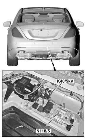
Vehicle view from the rear |
N118/5 | AdBlue® control unit |
K40/5kV | AdBlue® relay |
P14.40-2493-03
Location
The AdBlue® control unit is located in the trunk at the bottom right.
Task
The AdBlue® control unit controls the following functions based on a characteristics map:
- AdBlue® delivery
- injection
- antifreeze protection and return delivery
Input and output signals
The following input signals are evaluated by the AdBlue® control unit and the corresponding output signals issued:
Direct input signals
Direct output signals
CAN input signals
CAN output signals
Direct input signals
– circuit 31
- circuit 30 via circuit 87 for the AdBlue® relay
- AdBlue® fill level sensor sensor signal (A103/1b5)
- AdBlue® tank temperature sensor sensor signal (A103/1b1)
– detection of the power consumption for diagnosis of the AdBlue® delivery pump (A103/2m1)
Direct output signals
– supply of AdBlue® delivery pump
– supply and actuation of the AdBlue® extraction pump (A103/2m2)
- pulse width modulated signal for actuation of the AdBlue® delivery pump
- pulse width modulated signal for actuation of the AdBlue® metering valve (Y129)
– power supply for the AdBlue® container heating element (A103/1r1)
- power supply for the AdBlue® pressure line heating element (R7/1)
CAN input signals
CDI control unit (N3/9)
– request for reduction agent injection
– specification of the reduction agent quantity to be injected
- specification of the run-on time for the AdBlue® control unit
- diagnosis request
CAN output signals
CDI control unit (N3/9)
– quantity of reduction agent injected for NOx reduction
– reduction agent quantity injected for cooling the AdBlue® metering valve
– fill level status in the AdBlue® container
– requested diagnostic data
AdBlue® delivery
- feed line to the AdBlue® delivery pump to obtain the operating current consumption as a basis for the diagnosis of the AdBlue® delivery pump
– Actuation of AdBlue® delivery pump, to generate a pressure of 5 bar before and during the injection of reducing agent for nitrogen oxide (NOx) reduction. The delivery pressure can be set with the control unit software and may differ according to the particular variant.
– actuation of the AdBlue® delivery pump to generate a pressure of 5 bar before and during injection of the reducing agent for cooling the AdBlue® metering valve
- actuation of the AdBlue® metering valve for ventilation of the AdBlue® pressure line when filling the AdBlue® pressure line
Fuel injection
– actuation of the AdBlue® metering valve during the reduction agent injection for NOx reduction
Antifreeze protection and return delivery
- after "circuit 15 ON", the pump is given an initial run (warm-up) if the weather is cold. The initial run serves to remove the friction in cold weather, so that the required compaction can be made available as soon as possible when pressure is requested.
- actuation of the AdBlue® tank heating element to liquefy the AdBlue® reduction agent in the AdBlue® tank, which freezes at about –10°C
- actuation of the AdBlue® extraction pump (A103/2m2) for return delivery of the AdBlue® reduction agent in the pressure line to the AdBlue® tank during power-down of the AdBlue® control unit after "circuit 15 OFF"
The AdBlue® metering valve can be actuated without the float needle being opened. This serves to heat the valve.
The duration of the return flow of the AdBlue® reduction agent and the duration of the pressure line filling depend on the length of the pressure line.
The quantity of reducing agent injected by the AdBlue® metering valve is sent by the AdBlue® control unit over the drive train sensor CAN to the CDI control unit. This quantity is taken into account in the next computation of the quantity of reducing agent by the CDI control unit.
Designation | Unit | Values | Tolerance range | Remarks |
AdBlue® control unit (N118/5) | ||||
Control unit power-down | s | 10 ... 20 | ||
AdBlue® pressure sensor (A1032b1) | ||||
Model | Analog relative pressure sensor | |||
Power consumption | mA | 10 | ||
AdBlue® fill level sensor (A103/1b5) | ||||
Resistance between the sensor pins | kΩ | 10 | Not used with AdBlue® | |
Ω | approx. 300 | Used with AdBlue® | ||
Fill level | l | 28 ... 32 | ||
AdBlue® tank temperature sensor (A1031b1) | ||||
Model | NTC resistor (negative temperature coefficient) | |||
Resistor | kΩ | 55.33 | At -10°C | |
12.49 | at 20°C | |||
5.33 | at 40°C | |||
AdBlue® delivery pump (A1032m1) | ||||
Power consumption | A | < 1 | ||
Frequency | Hz | 100 | Pulse width modulated signal | |
Input resistance | kΩ | 2.35 | ||
AdBlue® extraction pump (A103/2m2) | ||||
Resistor | Ω | 3.98 | at 20°C | |
Power consumption | A | 2.2 | ||
AdBlue® metering valve (Y129) | ||||
Resistor | Ω | approx. 12 | at 20°C | |
Power consumption | A | <1.5 | ||
Inductance | mH | 14 | ||
Pulse of pulse width modulation (PWM) | Hz | 3.33 | Normal mode | |
AdBlue® pressure line heating element (R7/1) | ||||
Power consumption | A | Max. 10 | ||
Resistor | Ω | approx. 1.2 | Dependent on the pressure line length | |
Electrical output | W | max. 15 | ||
AdBlue® tank (A1031r1) heating element | ||||
Model | PTC resistor (positive temperature coefficient) | |||
Electrical output | W | max. 120 | ||
Power consumption | A | < max. 10 | ||
Input resistance | Ω | 1.2 |