GF14.30-D-2000H | Component description for electric air pump | 20.1.09 |
ENGINE 272.979 in MODEL 906
ENGINE 272.978 in MODEL 639
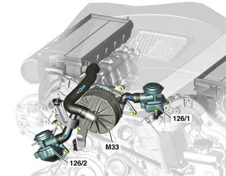
P14.30-2099-81
Illustrated on model 906
126/1 Left shutoff valve air injection (combination valve: check valve integrated)
126/2 Right shutoff valve air injection (combination valve: check valve integrated)
M33 Air injection motor
Location
The engine air injection is located upstream of the intake manifold.
Task
The engine air injection delivers the injected air to the exhaust side of the engine.
Design
Electrically operated vane-type pump. The injected air suctioned in from the air filter (clean air side) and delivered over 2 pressure fittings through the air shutoff valve to the outlet ducts.
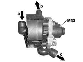
P14.30-2096-01
Function
Illustrated on model 906
a Air intake from the right air filter housing
b Injected air to the right air injection shutoff valve
c Injected air to the left air injection shutoff valve
M33 Air injection motor
The engine air injection is actuated for released air injection via the secondary air injection pump relay (K64) parallel to the air pump vacuum valve (Y59/2) for a maximum of 40 s. The power consumption is about 45 A at 13 V. The engine air injection suctions the injected air out of the air filter (clean air side) in the process and delivers it via two pressure fittings through the air shutoff valves to the outlet ducts. If the engine air injection runs for longer than about 4 minutes, e.g. due to wrong actuation, it will be damaged.
Following actuation, air injection remains locked. A new enable of the air injection will only take place if the catalytic convertors cool down again due to a sufficiently long stoppage of the engine. Therefore the engine air injection has sufficient time to cool off again.
The engine air injection can be deliberately actuated using Star Diagnosis for a maximum of two minutes. A cooling off time of at least 30 min should be maintained before the next actuation since the engine air injection will be damaged otherwise.