GF09.00-P-2000MD | Turbocharging, function | 7.5.08 |
ENGINE 266.980 in MODEL 169.034 /334, 245.234 as of model year 09 /AEJ 08 model refinement package

P09.40-2219-76
View of charge air path
1 Air filter
2 Charge air intake manifold
3 Turbocharger
4 Vacuum unit for boost pressure control flap
5 Charge air pipe upstream of charge air cooler
6 Charge air cooler
7 Charge air pipe downstream of charge air cooler
8 Charge air distribution pipe
B28 Pressure sensor (intake manifold air pressure)
B28/5 Pressure sensor downstream of air filter
B28/6 Pressure sensor upstream of throttle valve actuator
M16/6 Throttle valve actuator
A Intake air
B Charge air (uncooled)
C Charge air (cooled)
D Exhaust
Function requirements for forced induction - general
Circuit 87M ON (engine control ON)
Engine running
Forced induction, general
Cylinder filling efficiency is improved by forced induction. This raises the engine torque and engine power.
The fuel quantity corresponding to the increased air mass is metered by the ME-SFI [ME] control unit (N3/10).
When charging, the flow energy of the exhaust gases is used to drive the turbocharger.
The turbocharger draws in fresh air at the compressor inlet and passes this via the compressor outlet into the charge air pipe upstream of the charge air cooler.
The high speed of the compressor turbine wheel and the resultant high volume flow compresses the air in the charge air pipe upstream of the charge air cooler. The maximum boost pressure is 0.7 bar.
-----------------------------------------------------------------------------------------
The noise damper on the compressor outlet dampens the boost pressure fluctuations and the associated flow noises which occur for rapid changes of engine speed.
The compressed and heated charge air flows over the charge air pipe upstream of the charge air cooler to the charge air cooler. This cools the charge air and passes it on via the charge air pipe downstream of the charge air cooler to the intake manifold.
Forced induction function sequence
The function sequence is described in the following partial functions:
Boost pressure control function sequence
Deceleration air function sequence
-----------------------------------------------------------------------------------------
Boost pressure control function sequence
The boost pressure is controlled electro-pneumatically via the boost pressure control pressure transducer (Y31/5).
The pressure transducer is actuated performance map and load-dependent by the ME-SFI [ME] control unit for boost pressure control.
In full-load range, the maximum boost pressure is built up.
The boost pressure control is dependent on:
- Crankshaft position sensor (L5), motor speed
- Accelerator pedal sensor (B37), load request by driver
- Safety functions provide by the engine control, such as: knock control, transmission overload protection and overheating protection
In order to reduce the boost pressure the exhaust flow for the supercharger turbine drive is diverted via a bypass (wastegate) by opening the boost pressure control flap. The boost pressure control pressure transducer also actuates the boost pressure control flap vacuum unit with vacuum from the vacuum pump.
The vacuum unit opens the boost pressure control flap via a control rod which closes off the bypass. The boost pressure control valve enables the exhaust gas stream to bypass the turbine wheel (bypass), and the boost pressure is thus controlled and the speed of the turbine wheel limited.
In this way it is possible to adapt the boost pressure from a maximum of 0.7 bar to the current load requirements of the engine.
To monitor the current boost pressure, the pressure sensor upstream of the throttle valve (B28/6) sends an appropriate voltage pulse to the ME-SFI [ME] control unit.
The pressure sensor downstream of air filter (B28/5), located in the charge air intake manifold upstream of the turbocharger, serves the ME-SFI [ME] control unit to monitor the charging.
The charge air temperature in the intake manifold is detected by the intake air temperature sensor (B17) and sent to the ME-SFI [ME] control unit in the form of a voltage signal.
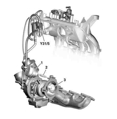
P09.40-2220-12
Illustrated is boost pressure control
1 Vacuum unit for boost pressure control flap
2 Control rod
3 Boost pressure control flap
Y31/5 Boost pressure control pressure transducer
Deceleration air function sequence
The turbochargers rotates by means of the inertia of masses of the shaft, compressor and turbine wheel after start of deceleration and briefly creates further boost pressure against the closed throttle valve.
Pressure peaks (brief howling) in the turbochargers are prevented by the deceleration air switchover valve (Y101).
If the ME-SFI [ME] control unit identifies the transition from load to deceleration operation, the switchover valve deceleration switchover is actuated.
The deceleration air switchover valve reacts by opening the bypass which bypasses the compressor impeller thereby reducing the boost pressure.
The deceleration air switchover valve closes in boost mode by means of an integrated spring.

P09.40-2218-12
Illustrated is divert air
1 Turbocharger
2 Deceleration air valve
3 Divert air line
4 Charge air distribution pipe
Y101 Divert air switchover valve
Referenced documents
- gf0761p6000md Component description for ME-SFI [ME] control unit
- pe0940p205097baa Electrical function schematic for boost pressure control
- pe0940p205097qa Electrical function schematic for boost pressure control