AR26.10-W-0010A | Assemble transmission | 27.2.12 |
TRANSMISSION 715.320 in MODEL 950.5 /6, 952.5 /6, 953.6, 954.5
TRANSMISSION 715.320 in MODEL 970, 972, 974, 976
TRANSMISSION 715.320 in MODEL 375.3

W26.10-1027-09
1 Gear shift cylinder (model 375.3, 970, 972, 974, 976 with code (GS1) "manual" gearshift)
2 Shift rod
3 Shift rod
4 Shift rod
5 Shift rod
6 Clip
7 Shift fork
8 Shift fork
9 Shift fork
10 Shift fork
11 Oil pipe
12 Screw plug
13 Spring
14 Spring
15 Catch bolt
16 Screw
17 Rear transmission housing
18 Reverse idler shaft
19 Screw
20 Retaining plate
21 Screw plug
42 Bearing shell of front countershaft
43 Shift cylinder
44 Gearshift piston with gearshift rod
45 Countershaft
46 Bearing shell
47 Compressed-air line
48 Banjo bolt
49 Sealing rings
50 Electrical connector
51 Cover
52 Retaining ring
53 Shift cover
54 Washer
55 Needle roller bearing
B3 Countershaft rpm sensor
B17 Vehicle speed sensor
S7 Reverse gear switch
S9 Neutral position switch
Y64 Shift force assistance solenoid valve
(model 375.3, 970, 972, 974, 976 with code (GS1) "Manual" gearshift)
22 Oil pump
23 Output flange
24 Spring
25 Oil strainer
26 Screw plug
27 Bearing bolt
28 Clutch servo assistance
29 Bearing shell
30 Pulse star
31 Main shaft
32 Drive shaft
33 Gear control valve
(model 375.3, 970, 972, 974, 976 with code (GS1) "manual" gearshift)
34 Bearing cover with shift shaft
35 Splitter group bearing bolt
36 Front transmission housing
37 Input shaft bearing shell
38 Shim
39 Drive shaft bearing cap
40 Countershaft bearing cover
41 Shim

W26.10-1028-06
11 Oil pipe
21 Screw plug
45 Countershaft
56 Reverse gear
57 Guide bolts
Arrow Reverse gear installation position
Modification notes
| Assemble | ||
1 | Install drive shaft bearing shell (37) and front countershaft bearing shell (42) | Use a suitable drift. Grease contact surface of bearing shells using lubricant. | |
2 | Preassemble drive shaft bearing cap (39) and countershaft bearing cap (40) | For better installation of oil pipe (11) and to secure bearing shells. Do not install sealing rings and shims (38, 41). | |
3 | Install radial shaft sealing ring and pilot bushing for shift piston with shift rod (44) | ||
Drift | |||
Lubricant | |||
4 | Assemble shift | ||
5 | Install shift cover (53) on the right with washer (54) and new sealing rings on the front of the transmission housing (36) | Note center position (neutral) of catch bolt. Pay attention to different lengths of bolts. | |
Clean sealing surfaces and coat with sealing compound. | |||
| |||
External torx set | |||
6 | Insert shift rods (5, 4, 3, 2) into front transmission housing (36) | Note installation sequence and installation position. | |
7 | Insert bearing cap with shift shaft (34) into front transmission housing (36) | Guide shift finger and plunger block of shift shaft into shift rods (5, 4, 3, 2). | |
Clean sealing surfaces and coat with sealing compound. | |||
| |||
External torx set | |||
8 | Install locking ring (52) and new cover (51) | Press shift rod simultaneously to the right. | |
Glue in cover using locking agent. | |||
9 | Preassemble shift piston with rubber sealing ring on shift rod | Only tighten finger-tight.Only secure the shift piston to the shift rod using the thread locking compound after the required shims have been determined. | |
10 | Install shift piston with shift rod (44) | ||
11 | Preassemble shift cylinder (43) with retaining ring | Preassemble without shims. | |
12 | Assemble countershaft (45) | ||
13 | Assemble main shaft (31) | ||
14 | Assemble (32) drive shaft | ||
15 | Mount main shaft (31) on drive shaft (32) | ||
16 | Attach lifting device to main shaft (31) and countershaft (45) | Lifting device | |
17 | Insert main shaft (31) together with drive shaft (32) and countershaft (45) into front transmission housing (36) using lifting device | Then detach the lifting device. | |
18 | Install pulse star (30) on drive shaft (32) | ||
19 | Install shift fork (7) | ||
20 | Install splitter group bearing pin (35) | Insert the splitter group bearing pin (35) using thread locking compound. | |
| |||
21 | Install oil pipe (11) | ||
22 | Install shift forks (8, 9, 10) and clip into shift rods (2, 3, 4, 5) | The clip (6) must engage securely on the shift rod (2). | |
23 | Install bearing shells (29, 46) in rear transmission housing (17) | The rear transmission housing (17) must be free of oil and grease in the area around the bearing shells (29, 46). | |
Grease contact surface of bearing shells (29, 46) using lubricant. | |||
24 | Push shop-made guide rod for oil pipe (11) through threaded hole of screw plug (21) | ||
| Steel rod for guiding the transmission oil pipe | ||
25 | Install reverse gear (56) and move into installation position (arrow) | ||
26 | Drive guide pins (57) into rear transmission housing (17) until they project approx. 5 mm above contact surface | ||
27 | Mount rear transmission housing (17) | Coat sealing surfaces with sealant. Insert shop-made guide rod into oil pipe (11). | |
28 | Install bearing bolt (27) | First screw in the bearing pins (27) on the left side of the transmission by max. one turn. | |
Insert bearing pin (27) with sealing compound. | |||
| |||
29 | Insert guide bolt (57) into front transmission housing (36) until flush | ||
30 | Install catch bolt (15), springs (13, 14) and screw plug (12) | | |
31 | Screw in bolts (16) around circumference of transmission | | |
32 | Pull shop-made guide rod out of threaded hole for screw plug (21) | ||
33 | Screw new screw plug (21) into rear transmission housing (17) | ||
34 | Install reverse idler shaft (18) and retainer (20) and secure in place using bolt (19) | | |
35 | Position transmission so it is horizontal | ||
36 | Install spring (24), oil strainer (25) and screw plug (26) | Replace sealing ring. | |
| |||
37 | Install output flange (23) | Install new radial shaft sealing rings. | |
38 | Remove shift cylinder (43) and shift piston | ||
39 | Press splitter group shift rod backwards | Turn input shaft (32) by hand until the splitter group is engaged. | |
40 | Detach drive shaft bearing cover (39) | External torx set | |
41 | Determine shim (38) for drive shaft bearing cap (39) | ||
Dial indicator | |||
Gage stand | |||
Thrust device | |||
42 | Install drive shaft bearing cap (39) and detach countershaft bearing cap (40) | ||
43 | Determine shim (41) for countershaft bearing cap (40) | ||
Dial indicator | |||
Gage stand | |||
Thrust device | |||
44 | Install countershaft bearing cap (40) | ||
45 | Determine shim for shift piston of splitter group | ||
46 | Determine size of shim for shift cylinder (43) of splitter group | ||
Internal extractor | |||
Countersupport | |||
Lubricant | |||
47 | Install shift cylinder (43) and shift piston for splitter group | ||
48 | Install central clutch release bearing | | |
49 | Install oil pump (22) and pressure relief valve | ||
50 | Install gear control valve (33) | Only applies to model 375.3, 970, 972, 974, 976 with code (GS1) "manual" gearshift. | |
51 | Install gear shift cylinder (1) | Only applies to model 375.3, 970, 972, 974, 976 with code (GS1) "manual" gearshift. | |
52 | Install shift force assist solenoid valve (Y64) | Model 375.3, 970, 972, 974, 976 only with code (GS1) "manual" gearshift. | |
53 | Install reverse gear switch (S7) | | |
54 | Install speed sensor (B17) | | |
55 | Install countershaft speed sensor (B3) | ||
56 | Install neutral position switch (S9) | ||
57 | Install clutch servo unit (28) | Vehicles with manufacture date up to 28.2.00 | |
Vehicles with manufacture date as of 1.3.00: | |||
without code (IY2) Hydraulic fluid as per sheet 345.0 | |||
with code (IY2) Hydraulic fluid as per sheet 345.0 |
Inspection and adjustment data: splitter unit (splitter group)
Number | Designation | Transmission | |
BE26.35-N-1001-01A | Adjustment dimension for gearshift piston of cascade box | mm | 0.3...0.5 |
BE26.35-N-1002-01A | Adjustment dimension for splitter box shift cylinder | mm | 0.4...0.5 |
Test and adjustment values for gear set
Number | Designation | Transmission | ||
BE26.50-N-1007-01G | Service data for drive-shaft bearings | Proof load | O | 2400 |
Spring preload | mm | 0.075 | ||
Tolerance | mm | 0.075 | ||
BE26.50-N-1008-01G | Adjustment values for countershaft bearing | Proof load | O | 2600 |
Spring preload | mm | 0.025 | ||
Tolerance | mm | 0.075 | ||
Clutch operating mechanism
Number | Designation | Model | Model | ||
BA25.20-N-1005-01N | Central clutch release bearing to transmission | Nm | 25 | 25 | |
Sensors
Number | Designation | Trans-mission | ||
BA26.19-N-1001-01C | Speed sensor to transmission output | Nm | 40 | |
BA26.19-N-1004-01C | Reverse gear switch to transmission housing | Nm | 60 | |
Splitter group
Number | Designation | Transmission | ||
BA26.35-N-1001-01A | Shift fork bearing bolt to transmission housing | Nm | 120 | |
Housing
Number | Designation | Trans-mission | |
BA26.40-N-1003-01D | Bearing bolt to shift fork (main shaft) | Nm | 120 |
BA26.40-N-1006-01D | Retaining panel of reverse shaft to transmission housing | Nm | 40 |
BA26.40-N-1008-01D | Splitter group shift lock to transmission housing | Nm | 30 |
BA26.40-N-1009-01D | Front transmission housing to rear transmission housing | Nm | 70 |
Transmission oil cooling, oil pump
Number | Designation | Transmission | ||
BA26.55-N-1006-01A | Screw plug, oil strainer to transmission housing | M38 | Nm | 75 |
M42 | Nm | 120 | ||
Shift mechanism
Number | Designation | Transmission | ||
BA26.60-N-1008-01F | Shift mechanism bearing cap to transmission housing | Nm | 25 | |


000 589 30 33 00
Internal puller
Counter stay
000 589 34 33 00
001 589 53 21 00
Dial indicator
External Torx set
001 589 76 09 00
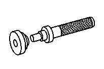


Drift
Dial indicator holder
714 589 05 15 00
343 589 00 40 00
715 589 00 35 00
Thrust device
Lifting device
714 589 00 59 00
Repair materials
Number | Designation | Order number |
BR00.45-Z-1015-01A | Loctite 5203 sealant | A 002 989 71 20 10 |
BR00.45-Z-1001-02A | Thread locking adhesive, Loctite 241 | A 002 989 94 71 |
BR00.45-Z-1133-02A | Loctite 243 | A 613 989 09 71 |
BR00.45-Z-1008-06A | Silicone-based grease | A 001 989 28 51 10 |
BR00.45-Z-1027-06A | Synthetic grease 50 g | A 001 989 32 51 10 |
Referenced documents
- ar2520w0300a Clutch servo unit removal and installation
- ar2520w0300b Clutch servo unit removal and installation
- ar2520w0300ba Clutch servo unit removal and installation
- ar2618w2000c Remove/install gear shift cylinder
- ar2618w2050a Remove/install gear control valve
- ar2619w0004a Remove/install neutral position switch
- ar2619w0005a Remove/install countershaft speed sensor
- ar2619w0015a Remove/install shift force assist solenoid valve
- ar2630w100001b Determine size of shim for input shaft bearing cap
- ar2630w100002b Determine size of shim for countershaft bearing cap
- ar2630w1010b Remove/install input shaft and countershaft bearing covers
- ar2635w100001a Determine shim for shift piston of splitter group
- ar2635w100002a Determine shim for cylindrical actuator of cascade box
- ar2635w100003b Remove/install radial shaft seal and pilot bushing for splitter group shift rod
- ar2635w1000b Remove/install shift rod and shift piston for splitter group
- ar2640w0007b Remove/install transmission output flange
- ar2650w0426b Assembling transmission main shaft
- ar2650w4744d Dismantle/assemble drive shaft.
- ar2650w4775d Disassemble, assemble countershaft
- ar2655w3000b Remove/install oil pump and pressure relief valve
- ar2660w6515f Disassemble/assemble gearshift system
- wf5850n261002a Steel rod for guiding the transmission oil pipe