
P01.30-2247-09
3 | Poly-V-belt | 13 | Intake manifold | B2/5 | Hot film mass air flow sensor | ||
6 | Air intake pipe | 15 | Coolant line | B6/1 | Camshaft Hall sensor | ||
7 | Right cylinder head cover | 16 | Camshaft sprockets | G2 | Alternator | ||
9 | Left cylinder head cover | 17 | Camshaft bearing bridges | T1/1-T1/4 | Cylinder 1 to 4 ignition coil | ||
12 | Chain tensioner | 18 | Oil filter housing with oil water heat exchanger | T1/5-T1/8 | Cylinder 5 to 8 ignition coil |
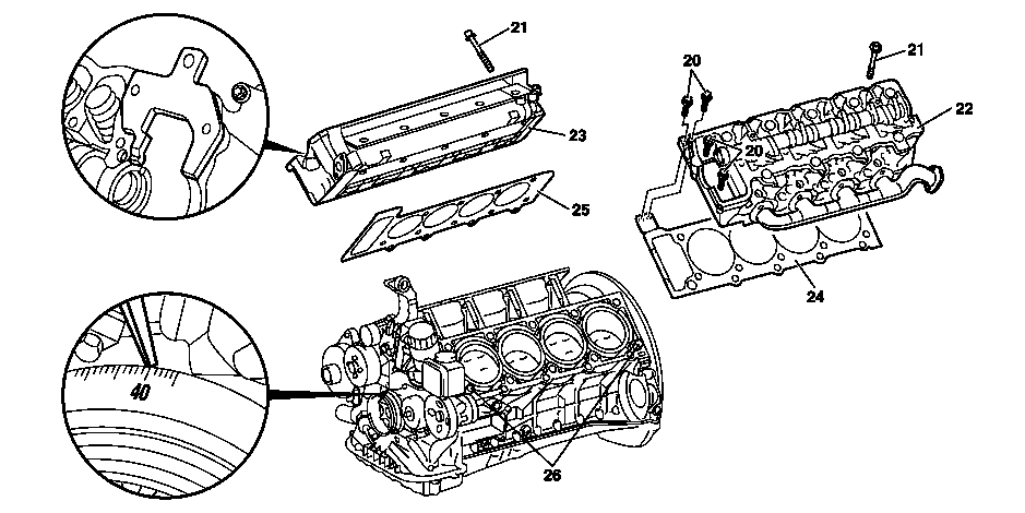
P01.30-2248-09
20 | Bolts | 23 | Right cylinder head | 25 | Right cylinder head seal | ||
21 | Cylinder head bolts | 24 | Left cylinder head seal | 26 | Fitting sleeves | ||
22 | Left cylinder head |
| Remove/install | ||
Danger | Risk of death caused by vehicle slipping or toppling off of the lifting platform. | Align vehicle between vehicle lift columns and position the four support plates at the vehicle lift support points specified by the vehicle manufacturer. | |
Warning | Risk of injury to skin and eyes suffering scalding from contact with hot coolantspray. Risk of poisoning from swallowing coolant. | Do not open cooling system unless coolant temperature is below 90 °C. Open cap slowly and release the pressure. Do not pour coolant into beverage containers. | |
Danger | Risk of explosion caused by fuel igniting, risk of poisoning caused by inhaling and swallowing fuel as well as risk of injury to eyes and skin caused by contactwith fuel. | No fires, sparks, open flames or smoking. Pour fuels into suitable and appropriately marked containers only. | |
Topical note | Notes on self-locking nuts and bolts | ||
Danger | Risk of fire/risk of explosion due to short circuit and escaping oxyhydrogen gas. Risk of (burn) injury caused by caustic burns to eyes, skin and mucous membranes from battery electrolyte/mist, short circuit and arcing. Risk of poisoning caused by swallowing battery electrolyte or absorption of lead through the skin or body orifices. Risk of death due to voltage U >= 30 V AC and U >= 60 V DC. | No fires, sparks, open flames, or smoking. Wear acid-resistant gloves, clothing, and glasses. Pour battery acid only into suitable and appropriately marked containers. | |
1 | Disconnect ground line of battery | ||
Topical note | Notes on battery | ||
| |||
Vehicles with Keyless Go, Code 889: | |||
2 | Remove lower engine compartment paneling | ||
3 | Drain coolant at radiator | ||
4 | Remove partition wall between wheel wells | ||
5 | Remove engine cover | ||
6 | Remove hot film mass air flow sensor (B2/5) with air intake pipe | ||
7 | Relieve fuel pressure with pressure hose via service valve | ||
Pressure hose | |||
8 | Detach fuel feed line from the fuel distributor | Collect escaping fuel with an absorbent rag. | |
Fuel feed line to fuel distributor | |||
9 | Remove ignition coil for cylinder 1 to 4 (T1/1-T1/4) and ignition coil for cylinder 5 to 8 (T1/5-T1/8) | ||
10 | Remove the right cylinder head cover (7) and the left cylinder head cover (9) | ||
11 | Remove air pump | ||
12 | Remove intake manifold (13) | ||
Installation: | |||
13 | Remove camshaft Hall sensor (B6/1) | ||
Only when removing the right cylinder head (23). | |||
14 | Remove poly-V-belt (3) | ||
Only when removing the left cylinder head (22). | |||
15 | Remove coolant line (15) from left cylinder head (22) on firewall | Engage the safety spring in the grid marking with the screwdriver and remove the coolant line. | |
Installation: Replace O-ring. Before installing the coolant line, bring the safety spring into basic position. | |||
16 | Disconnect exhaust system from exhaust manifold | Installation: | |
Flange connection of exhaust manifold and front exhaust pipes | |||
17 | Rotate engine at crankshaft center bolt in direction of engine rotation to a 40° crankshaft angle downstream of after ignition TDC on the first cylinder | Do not reverse crank the engine. | |
The groove on the camshaft must point in the direction of "Inner-V". | |||
18 | Lock the camshaft with the fixing plate | Right plate: | |
Left plate: | |||
Fixing plate | |||
Arresting plate | |||
19 | Unscrew the screws in the oil filter housing with oil water heat exchanger (18) | ||
Only when removing the left cylinder head (22). | |||
20 | Remove chain tensioner (12) | ||
Place the alternator (G2) with connected lines to one side. | |||
21 | Detach camshaft sprockets (16) from the camshaft | Check engine valve timing | |
Set basic position of camshafts | |||
| |||
Right camshaft sprocket: | |||
Left camshaft sprocket: | |||
Installation: Check basic position of camshafts. | |||
Camshaft sprocket bolt | |||
Open-end wrench | |||
Insertion tool | |||
Torque wrench | |||
after test, if necessary | |||
| |||
Set basic position of camshaft | |||
22 | Remove camshaft bearing bridges (17) | ||
23 | Unscrew screws/bolts (20) | Screw/bolt, cylinder head to timing case cover | |
24 | Loosen cylinder head bolts (21) in stages and remove them | Slackening diagram for cylinder head bolts | |
Tightening specifications for cylinder head bolts | |||
| |||
Installation: | |||
Bolt, cylinder head to crankcase | |||
Screwdriver bit | |||
25 | Remove cylinder head | ||
Topical note | Information on applying sealant to cylinder head gasket | ||
Information on cylinder head contact surface | |||
Notes on assigning the cylinder head gaskets | |||
Installation: Pay attention to fitting sleeves (26) for fitting the cylinder head. | |||
Sealant, Loctite 5970, 50 ml | |||
| Clean | ||
26 | Clean the threaded holes and sealing surfaces of the cylinder crankcase and cylinder heads | Remove sealant | |
| |||
Loctite 7200 | |||
Loctite 7063 (400 ml) cleaning spray | |||
| Check | ||
27 | Check cylinder head screws (21) | ||
Cylinder head bolt | |||
28 | Check cylinder crankcase and cylinder head for cracks, shrink holes and flatness | Sealing surfaces of the cylinder crankcase and cylinder head are provided with an 0.8 mm thick silicone layer during series production. Silicone sealant is applied in the gasket area when carrying out repairs only if shrink holes are present. The sealant must be applied within 10 minutes. | |
Sealant, Loctite 5970, 50 ml | |||
29 | Install in the reverse order | ||
30 | Check cooling system for leaktightness | ||
Warning | Risk of accident from vehicle starting off by itself when engine running. Risk of injury (bruises and burns) resulting from working on the engine while it is being started or when it is running. | Secure vehicle to prevent it from starting off by itself. Wear closed and snug-fitting work clothes. Do not touch hot or rotating parts. | |
31 | Carry out engine test run and check engine for leaktightness while it is running | | |
32 | Read out fault memory and clear | ||
| Connect Star Diagnosis | ||
Stored faults entries which may have been caused by disconnecting lines or by a simulation must be erased in the fault memory after completing the work. |


001 589 72 21 00
Torque wrench
112 589 00 32 00
Fixing plate
112 589 01 03 00
Insertion tool
112 589 01 32 00
Arresting plate


112 589 00 01 00
Open-end wrench
000 589 03 10 00
Screwdriver bit
119 589 04 63 00
Pressure hose
Referenced documents
- ad0000p200004a Connect STAR DIAGNOSIS and read out fault memory
- ad0000p200004a
- ah0000n000101a Notes on self-locking nuts and bolts
- ah0130p100004rx Information on applying sealant to cylinder head gasket
- ah0130p100005a Information on cylinder head contact surface
- ah0130p100006v Notes on assigning the cylinder head gaskets
- ah5410p000101a
- ah5410p000101a Notes on battery
- ar0100p005001a Remove sealant
- ar0110p2405rt Remove/install engine cover
- ar0110p2405rtb Remove/install engine cover
- ar0120p5014rt Remove/install cylinder head cover
- ar0130p580003b Check cylinder head bolts
- ar0130p580007b Tightening instructions for cylinder head bolts
- ar0130p580009b Slackening diagram for cylinder head bolts
- ar0510p6858rt Checking engine valve timing
- ar0510p7800rt Remove/install chain tensioner
- ar0520p6020rt Setting basic position of camshafts
- ar0520p7103rt Remove/install camshaft bearing bridge
- ar0703p146001gz Reduce fuel pressure through service valve
- ar0707p1454rt Remove/install hot film mass air flow sensor together with air intake pipe
- ar0920p1310rt Remove/install intake manifold
- ar1322p1202rt Remove/install poly V-belt
- ar1430p7251rt Remove/install air pump
- ar1430p7251rts Remove, install air pump
- ar1510p2000rt Remove/install camshaft Hall sensor
- ar1512p2003rt Remove/install ignition coils
- ar1830p3481rt Remove/install oil-water heat exchanger at oil filter
- ar2000p1010gz Inspect cooling system for leaks
- ar2000p1010gzb Inspect cooling system for leaks
- ar2000p1010gzc Inspecting cooling system for leaks
- ar2000p1010gzs Inspect cooling system for leaks
- ar2000p1142gz Drain/pour in coolant
- ar2000p1142gzb Drain/fill in coolant
- ar2000p1142gzc Drain/pour in coolant
- ar2000p1142gzd Drain, fill coolant
- ar2000p1142gzs Drain/pour in coolant
- ar5410p0003rt Disconnect/connect battery ground line
- ar6120p1105rt Remove/install bottom engine compartment paneling
- ar6230p2400rt Remove/install partition wall between wheelhouses
- as0000z000501a Risk of accident from vehicle starting off by itself when engine running. Risk of injury (bruises and burns) resulting from working on the engine while it is being started or when it is running.
- as0000z001001a Risk of death caused by vehicle slipping or toppling off of the lifting platform.
- as2000z000101a Risk of injury to skin and eyes suffering scalding from contact with hot coolantspray. Risk of poisoning from swallowing coolant.
- as4700z000101a Risk of explosion caused by fuel igniting, risk of poisoning caused by inhaling and swallowing fuel as well as risk of injury to eyes and skin caused by contactwith fuel.
- as5410z000101a Risk of fire/risk of explosion due to short circuit and escaping oxyhydrogen gas. Risk of (burn) injury caused by caustic burns to eyes, skin and mucous membranes from battery electrolyte/mist, short circuit and arcing. Risk of