ENGINE | 275, 279, 285 |

124 589 00 91 00
Test cap
Shown on engine 275, 285 |

1 | Connect connections (A, B) with the service connections of the charge air cooler. |
P20.00-2133-04

2 | Close all valves (C, D, H, HA, O, P) on control unit, Y-fitting and vacuum box. |
P20.00-2134-06

All connections described in the operation steps 3 to 5 remain intact during the whole filling process. Swapping around of the hoses (E, J, S) leads to destruction of the ventilation devices.
3 | Connect coolant feed (J) with connection (N). |
4 | Connect coolant drain (E) with connection (F). |
5 | Lay waste air hose (S) in receptacle. |
P20.00-2135-06
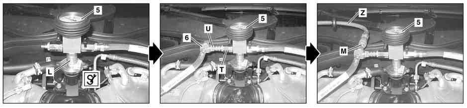
P20.00-2136-07
6 | Connect control unit (5) with the test connection - connection (L) to test connection. ENGINE 275, 285 |
8 |
Connect venturi nozzle (6) with control unit (5) - connection (U) to connection (T). |
9 |
Connect compressed air (Z) with venturi nozzle (6) - compressed air (Z) to connection (M). |
Audible air outlet is normal. |

10 | Generate vacuum in control unit (5) - open valve (P). |
11 | Suction in coolant up to the control unit (5) through regulation at valve (O) (arrow). Close valve (O) again afterwards. |
P20.00-2138-04

12 | Check low-temperature circuit for leaktightness - close valve (P). |
The unchanged display (arrow) on the pressure measuring device shows maintenance of the vacuum and therefore the leaktightness of the low-temperature circuit. |
P20.00-2137-04
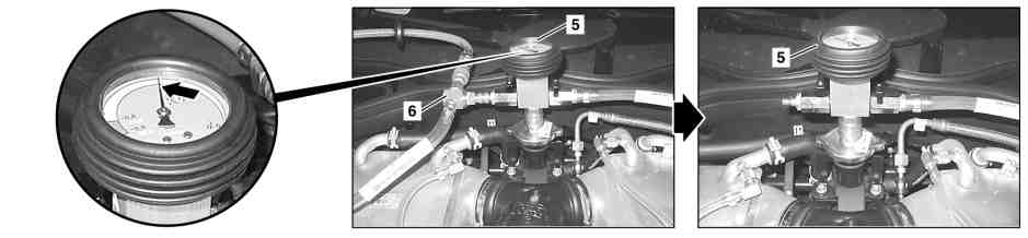
P20.00-2139-07
13 |
Disconnect venturi nozzle (6) from control unit (5). |
The display on the pressure measuring device (arrow) must still show a vacuum after ending the preparatory work. |