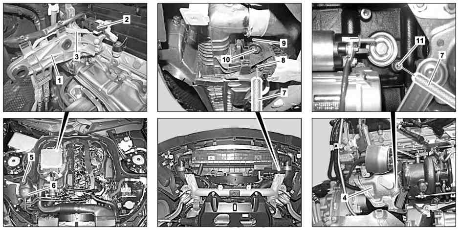
P20.00-2456-09
1 | Air filter housing bracket | 5 | Cap | 9 | Radiator | ||
2 | Electrical connector | 6 | Coolant expansion reservoir | 10 | Drain screw for radiator | ||
3 | Electrical line | 7 | Drain hose | 11 | Crankcase drain screw | ||
4 | Heat shield | 8 | Fitting on radiator |
Danger | Risk of death when working on component parts and systems with U >= 30 V alternating voltage (AC) or U >= 60 V direct voltage (DC) | Do not touch damaged or defective live component parts and lines or non-insulated electrical connections and lines. | |
Warning | Risk of injury to skin and eyes suffering scalding from contact with hot coolantspray. Risk of poisoning from swallowing coolant. | Do not open cooling system unless coolant temperature is below 90 °C. Open cap slowly and release the pressure. Do not pour coolant into beverage containers. | |
Topical note | General information on handling vehicles with high-voltage on-board electrical system and/or lithium-ion battery and/or gaseous-fuel drive system | ||
Topical note | Notes on coolant | ||
Notes on coolant level | |||
| Remove | ||
1 | Perform enable for the high voltage on-board electrical system | ||
2 | Remove DPF differential pressure sensor from air filter housing holder (1) | ||
Do not remove the DPF differential pressure sensor from the pressure lines for the CAT diesel particulate filter unit. | |||
3 | Unclip electrical connection (2) from holder | ||
4 | Disconnect electrical connection (2) | ||
5 | Remove electrical line (3) on air filter housing bracket (1) | ||
6 | Unscrew cap (5) from coolant expansion reservoir (6) | Unscrew cap (5) slowly and relieve overpressure. | |
7 | Remove bottom section of soundproofing | ||
8 | Remove catalytic converter diesel particulate filter unit | ||
9 | Remove heat shield (4) | ||
Drain coolant at crankcase | |||
10 | Protect power electronics control unit and electrical line of high voltage on-board electrical system against escaping coolant | ||
11 | Push drain hose (7) onto crankcase drain screw (11) | ||
12 | Loosen crankcase drain screw (11) and drain off coolant | Collect coolant in a suitable container. | |
Observe regulations to dispose of coolant. | |||
13 | Tighten crankcase drain screw (11) and detach drain hose (7) | Coolant drain plug on crankcase | |
Drain off coolant from cooler (9) | |||
14 | Push drain hose (7) onto fitting on the radiator (8) | ||
15 | Unfasten radiator drain screw (10) at radiator (9) and drain off coolant | | |
Collect coolant in a suitable container. | |||
Observe regulations to dispose of coolant. | |||
16 | Switch on ignition for about 5 seconds and then switch off again | Repeat process x 2 after a waiting time of approx. 30 s to thus empty low-temperature coolant circuit. | |
17 | Tighten down radiator drain screw (10) and pull out drain hose (7) | ||
Pour in | |||
18 | Pour in coolant and ventilate engine cooling system | ||
| Anticorrosion/antifreeze agents (Sheet 325.0) | ||
| Coolant specifications | ||
Use clean coolant again. | |||
Coolant mixing ratio | |||
NTKL Adaption | |||
Electric vacuum pump | |||
Test cap | |||
Cooler vacuum filling device | |||
19 | Switch on ignition for about 5 seconds and then switch off again | Repeat process x 2 after a waiting time of approx. 30 s to thus fill and bleed low-temperature coolant circuit. | |
| Install | ||
20 | Check engine cooling system for leaktightness | ||
21 | Install heat shield (4) | ||
22 | Install catalytic converter diesel particulate filter unit | ||
23 | Install bottom section of soundproofing | ||
24 | Contact the electrical connection (2), clip into the holder and attach electrical line (3) to air filter housing holder (1) | ||
25 | Remove DPF differential pressure sensor from air filter housing holder (1) | ||
26 | Perform high voltage on-board electrical system commissioning | ||
| Check | ||
Warning | Risk of accident from vehicle starting off by itself when engine running. Risk of injury (bruises and burns) resulting from working on the engine while it is being started or when it is running. | Secure vehicle to prevent it from starting off by itself. Wear closed and snug-fitting work clothes. Do not touch hot or rotating parts. | |
27 | Perform an engine test run and check engine cooling system for proper operation |


285 589 01 21 00
NTKL Adaption
210 589 00 91 00
Test cap
285 589 02 21 00
Electric vacuum pump
285 589 00 21 00
Cooler vacuum filling device
Henviste dokumenter
- ah0000z030001a Generelle oplysninger ved køretøjer med højvoltsnet og/eller litium-ion-batteri og/eller gasdrivsystem samt personligt beskyttelsesudstyr
- ah2000n208001a Oplysninger om kølervæske
- ah2000p114201cw Oplysninger kølervæskestand
- ar0704p0012cd
- ar2000p1010oma
- ar2000p114204a
- ar4910p5501cd
- ar5410p1150eh Skift til spændingsløs tilstand/ibrugtagning af køretøjets højvoltsnet
- ar9430p5300ew
- as0000z000501a Fare for ulykke ved automatisk igangsætning når motoren kører. Fare for personskade på grund af knusning og forbrænding, hvis der arbejdes mens motoren startes eller kører
- as0000z003501a Livsfare ved arbejde på komponenter og systemer med U >= 30 V vekselspænding (AC) eller U >= 60 V jævnspænding (DC)
- as2000z000101a Risiko for skoldningsskader på hud og øjne pga. sprøjtende, varm kølervæske. Risiko for forgiftning ved indtagelse af kølervæske
- bb0040p031001a
- bb0040p032500a