GF35.50-W-2003A | Raising trailing axle, function | 28.4.99 |
REAR AXLE 749.011 with CODE (AN6) Twin-tired trailing axle (Nummek)
Domestic
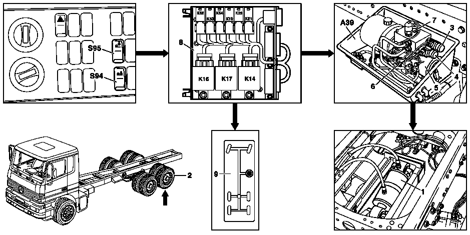
W35.50-1020-09
1 Hydraulic cylinder
2 Trailing axle
3 Lift solenoid valve
4 Lowering solenoid valve
5 Motor
6 Hydraulic pump relay
7 Pressure limiting switch
8 Nummek axle control module
9 Trailing axle display field
K52 Lowering relay
K53 30 km/h lowering relay
K54 30 km/h self-holding relay
S94 Lift axle switch
S95 Lower axle ON switch
A39 Nummek axle
K14 Starting-off aid time relay
K16 Lower time relay
K17 Drop-off delay time relay
K19 Lowering end shutoff relay
K20 Lowering relay
K21 Lifting end shutoff relay
The lowered trailing axle can be raised by switching on the lower axle ON switch (S95) and actuating the lift axle switch (S94).
Function sequence
Function prerequisites:
Ignition: ON
Trailing axle lowered
Drive axle load below 9 t (vehicle empty or only partially loaded)
When the ignition is turned on input S and input terminal 15 of the drop-off delay time relay (K17) are supplied with power. The relay picks up and power is supplied from terminal 30 at the lower axle ON switch (S95).
The drop-off delay time relay (K17) has a time delay of 15 seconds.
-----------------------------------------------------------------------------------------
This allows the driver to switch on terminal 15 again up to 15 seconds after switching off the engine in order to prevent the trailing axle dropping (rail gate circuit).
If the lower axle ON switch (S95) is pressed up, the lower axle ON switch (S95) closes. The lowering relay (K52) picks up immediately and interrupts the circuit for lowering the axle. Furthermore, the input S of the lower time relay (K16) is supplied with power. The relay picks up.
If the drop-off delay time relay (K17) fails (15 seconds after switching off terminal 15), the lowering time relay (K16) ensures power is supplied for 15 seconds to lower the trailing axle.
-----------------------------------------------------------------------------------------
At the same time, power is supplied at the lift axle switch (S94) via the NC contact of the 30 km/h limit value sensor A56 and at the starting-off aid time relay (K14), input terminal 15.
If the lift axle switch (S94) is pressed, input S of the starting-off aid time relay (K14) is supplied with power. The relay picks up and switches to self-holding via the overload switch (S96).
The lift solenoid valve (3) is supplied with power via the NC contact of the lifting end shutoff relay (K21). The hydraulic pump relay (6) is supplied with power via the NC contact of the lowering relay (K20).
The hydraulic pump relay (6) picks up and switches B+ to the motor (5). The motor is switched on and drives the pump component of the hydraulic pump in the hydraulics box. The trailing axle is raised.
The indicator lamp inversion relay K1 and indicator lamp self-holding relay K3 are simultaneously supplied with power via the diode box V10. Both relays pick up and the display in the trailing axle display field (9) lights up.
At a pressure of 128 bar the pressure limiting switch (6) closes. The lifting end shutoff relay (K21) is supplied with power via the diode box V1 and the relay switches to self-hold.
As a result, the power supply is interrupted to the lift solenoid valve (3) and the hydraulic pump relay (6) and they drop out. The motor (5) of the hydraulic pump is switched off.
If the overload switch is switched due to uneven road surfaces when the vehicle is moving, it is buffered by the OFF delay of the starting-off aid time relay (K14).
Referenced documents
- gf3550w2000a Lowering trailing axle, function
- gf3550w2105a Solenoid valve position/task/function
- gf3550w2106a Overload switch position/task/function
- gf3550w2107a Pressure limiting switch, position/task/function
- gf5420w3000a Nummek axle control module, position/design