D08.00-A014-79
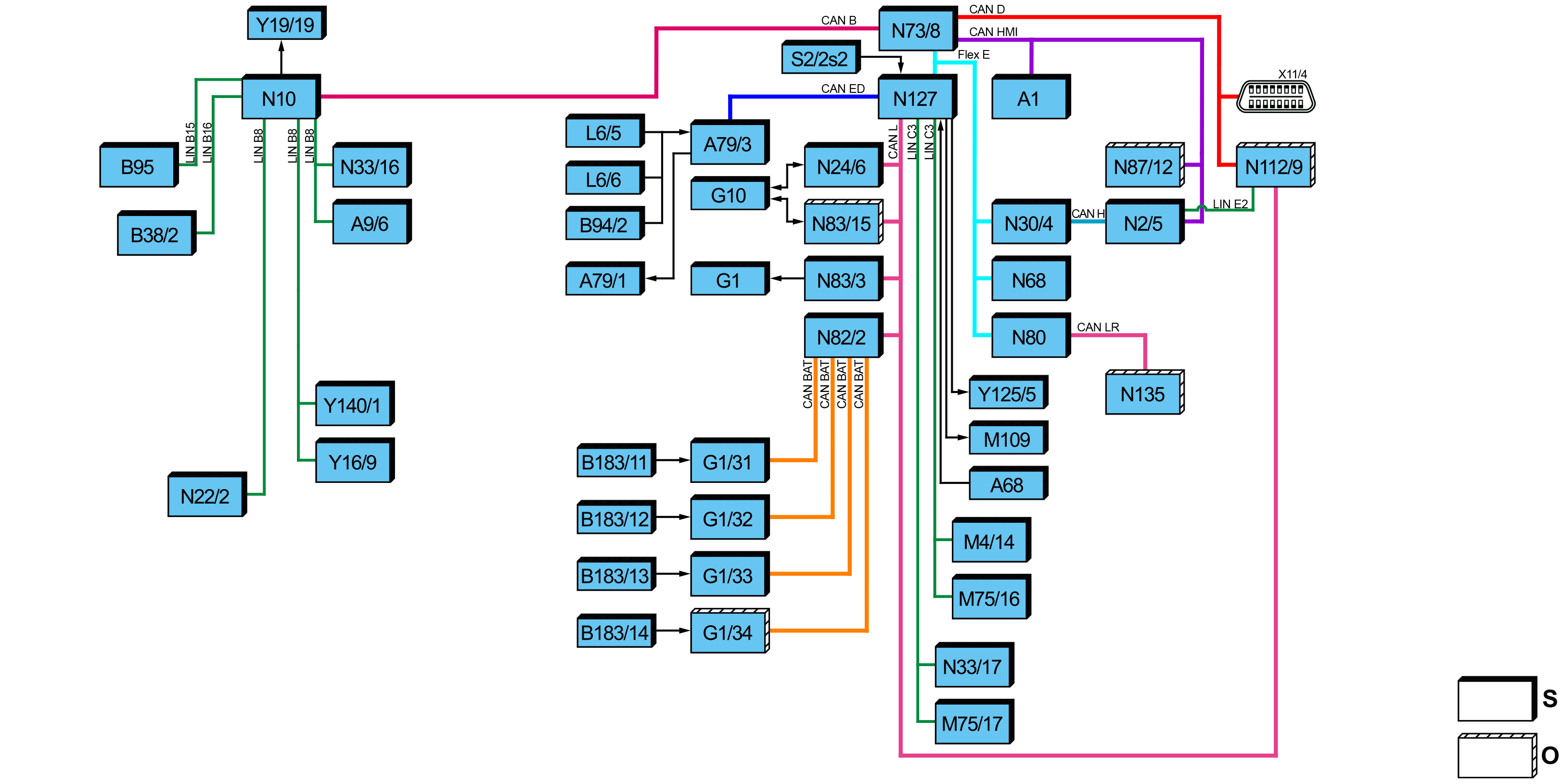
Electric vehicle, block diagram |
A1 | Instrument cluster | N73/8 | Electronic ignition lock (EZS) control unit | |
A9/6 | Electric refrigerant compressor | N80 | Steering column tube module (MRM) control unit | |
A68 | Accelerator pedal module | N82/2 | Battery management system control unit | |
A79/1 | Electric machine 1 | N83/3 | DC/DC converter control unit | |
A79/3 | Power electronics control unit | N83/15 | Alternating current charger for high-voltage battery | |
B38/2 | Rain and light sensor (with code JF1 (Rain sensor)) | N87/12 | Radio (with code E1O (Entrance radio)) | |
B94/2 | Electric machine temperature sensor | N112/9 | HERMES control unit (with code JH3 (Communication module (LTE) for digital services)) | |
B95 | Battery sensor | N127 | Drivetrain control unit | |
B183/11 | High-voltage battery temperature sensor 1 | N135 | Steering wheel electronics | |
B183/12 | High-voltage battery temperature sensor 2 | S2/2s2 | Transmission mode button | |
B183/13 | High-voltage battery temperature sensor 3 | X11/4 | Diagnostic connector | |
B183/14 | High-voltage battery temperature sensor 4 (with code E4T (High-voltage battery (47 kWh))) | Y16/9 | Condensation prevention switchover valve | |
G1 | On-board electrical system battery | Y19/19 | High-voltage battery cooling system evaporator shutoff valve | |
G1/31 | High-voltage battery 1 | Y125/5 | High-voltage battery cooling system switchover valve | |
G1/32 | High-voltage battery 2 | Y140/1 | Expansion valve | |
G1/33 | High-voltage battery 3 | CAN B | Interior CAN | |
G1/34 | High-voltage battery 4 (with code E4T (High-voltage battery (47 kWh))) | CAN BAT | Battery management system CAN | |
G10 | DC/AC charging vehicle socket | CAN D | Diagnostic CAN | |
L6/5 | Left electric machine rpm sensor | CAN ED | Electric drive system CAN | |
L6/6 | Right electric machine rpm sensor | CAN H | Vehicle dynamics CAN | |
M4/14 | Cooler fan | CAN HMI | User interface CAN | |
M75/16 | Low-temperature circuit coolant circulation pump 1 | CAN L | Hybrid CAN | |
M75/17 | Low-temperature circuit coolant circulation pump 2 | CAN LR | Steering wheel CAN | |
M109 | Electric vacuum pump | Flex E | Chassis FlexRay | |
N2/5 | Supplemental restraint system (SRS) control unit | LIN B8 | Climate control LIN | |
N10 | SAM control unit | LIN B15 | Battery sensor LIN | |
N22/2 | Automatic air conditioning control and operating unit (with code HH9 (Semi-automatically controlled air conditioning, TEMPMATIC)) | LIN B16 | Rain and light sensor LIN | |
N24/6 | Direct current charge connection unit | LIN C3 | Drivetrain LIN | |
N30/4 | ESP® control unit | LIN E2 | Seat occupied recognition LIN | |
N33/16 | High-voltage PTC heater control unit | O | Optional | |
N33/17 | Battery heater control unit | S | Default | |
N68 | Electrical power steering (ES) control unit |
The interlock circuit and high-voltage on-board electrical system are not shown in the block diagram.
Interlock circuit
The interlock circuit is used as contact protection to protect people against inadvertent contact with high-voltage components. The interlock is an anticipatory contact, which opens a little before the high-voltage connection when disconnecting a high-voltage connection. In this way timely discharging of the high voltage intermediate circuit is achieved by the control units of the high-voltage components.
The interlock circuit detects open lines or access points in the high-voltage on-board electrical system. For this purpose, a 12-V/88 Hz interlock signal is looped through all component parts of the high-voltage on-board electrical system that can be removed or opened. To do this, there is a jumper in each removable high-voltage plug connection which interrupts the interlock circuit when the high-voltage plug connection is detached.
Further information on the interlock circuit and high-voltage on-board electrical system can be found in the separate function description "High-voltage on-board electrical system function".
Function description for the electric vehicle, general points
The electric vehicle function description includes the control and monitoring of the electric machine 1 (A79/1) and of the high-voltage on-board electrical system. The master control unit is the powertrain control unit (N127), which contains the energy management and this coordinates all energy influences and torques in the electric vehicle.
The electric vehicle is driven exclusively by an electric machine. The electrical energy for this is provided by 3 lithium-ion high-voltage batteries that are switched at the same time, which were supercharged previously via the AC charger for the high-voltage battery (N83/15) during steady-state charging.
The high-voltage batteries have a maximum capacity of 41.4 kWh. To optimize the longevity of the performance of the battery pack, 35.2 kWh is available for the operating status. The electric vehicle can be charged at a mains socket, a public charging station, or a wallbox charging station. When charging at a mains outlet, the charging current must be limited if necessary to ensure that the local power network is not overloaded.
Further information on the charging of the high-voltage batteries can be found in the separate function description "Stationary charging function".
The document includes in detail the following information:
Electric drive
High-voltage on-board electrical system
Energy management
Drive programs "C", "E", "E+"
Speed limit
Occupancy detection
Towing and reversing
Electric drive
The electric drive consists of the electric powertrain, to which the electric machine 1, the transmission as well as the power electronics control unit belong.
Further information is contained in the separate function description "electric drive function" and "electric motor component description."
High-voltage on-board electrical system
The high-voltage on-board electrical system describes both the charging of the high-voltage batteries and the monitoring, cooling, and networking of the high voltage components.
Further information can be found in the separate function descriptions "Stationary charging function" and "High-voltage on-board electrical system cooling function".
Energy management
High-voltage on-board electrical system energy management manages the provision (supply) and consumption (balance) of electrical energy.
Further information can be found in the separate function description "High-voltage on-board electrical system function".
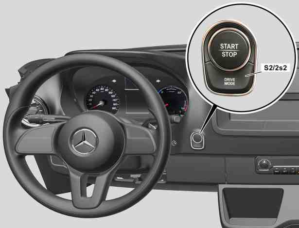
Drive program selection |
S2/2s2 | Transmission mode button |
D08.00-A017-76
Drive programs "C", "E", "E+"
3 different drive programs are available. At the start, the base drive program "E" (Economy) is active.
The two programs "C" (Comfort) and "E+" (Economy Plus) can be selected via the drive program button (S2/2s2) in the instrument panel.
In the multifunction display of the instrument cluster, the selected drive program is shown on the bottom right.
Symbol | Designation | Properties |
C | Comfort | Max. 85 kW, max. 300 Nm, direct response time, dynamic acceleration possible, full heating and climate control output to the disadvantage of the range, especially at low temperatures < 0 °C |
E | Economy | Max. 85 kW, max. 300 Nm, balanced response time, moderate heating output at low temperatures and slight reduction in climate control output at higher temperatures to the benefit of the range |
E+ | Economy Plus | Maximum 70 kW, maximum 270 Nm, delayed response time, minimum heating and climate control output, ensuring maximum range |
The drive programs have different features in the mileage, in the response time of the accelerator pedal, and in the heating and climate control output. Considered together, these features can lead to different ranges of the vehicle.
The range can be optimized via the drive program "E+". For this purpose, the maximum output of electric machine 1 is throttled at 70 kW and 270 Nm. The heating and climate control components for the driver's cab are controlled energy-consciously depending on the vehicle exterior temperature and vehicle interior temperature to achieve the best possible range. Because of the reduced heating output, a low blower setting should be selected consciously. The response time of the accelerator pedal is delayed so that sharp acceleration is prevented.
For all three drive programs, a defrost function is ensured for the windows. The individual drive programs have the following further features:
"C" ("Comfort") drive program
The entirety of the available performance can be accessed via the accelerator pedal module.
Controllability in the vehicle speed range is improved.
"E" ("Economy") drive program
Except at full load, the vehicle starts off forwards more smoothly.
Reduced performance at the accelerator pedal module increased controllability. This supports an even and energy-optimized driving style.
The wheels do not spin as easily when accelerating.
Full output only when using the kickdown.
"E+" ("Economy Plus") drive program
Reduced torque, speed reduction and greatly reduced output. A particularly efficient and uniform driving style is thus supported.
Except at full load, the vehicle starts off forwards more smoothly.
The wheels do not spin as easily when accelerating.
Particularly efficient overrun mode.
Full output only when using the kickdown.
The output of the A/C and heater is reduced.
The drive program "Comfort" can optionally be deactivated ex works (with code E1P (Comfort drive program deactivated)). Here, with comfort limitation in the heating and climate control output, an optimum range of the vehicle is ensured. Where "C" is selected via the drive program button, the permanent deactivation is indicated to the driver in the instrument cluster.
Speed limit
The eSprinter has as standard a speed limitation of 80 km/h. The speed limitations 100 km/h and 120 km/h are optionally available, suitable for the respective application.
A max. speed of 80 km/h fulfills all requirements in urban traffic and in conurbations; at the same time, it conserves energy and increases the range. Speeds up to 120 km/h are possible if a higher speed is required.
If the vehicle is limited to a maximum speed of 120 km/h, driving downhill on the freeway, for example, may cause the maximum approved speed to be exceeded due to the dead weight.
To prevent damage to the electrical powertrain, a message is displayed in the multifunction display of the instrument cluster indicating "Maximum speed reached, reduce speed" (not display text). A warning tone also sounds. When this message is displayed, the vehicle must be braked actively.
Occupancy detection
Occupancy detection is an important safety feature with emobility. Because the vehicle is so quite at a standstill, it can occur that the driver leaves the vehicle unintentionally while it is still ready to drive.
Fundamentally, a ready-to-drive vehicle is indicated in the multifunction display of the instrument cluster via the "READY" display. The seat belt buckle and the driver's door are controlled via the security system. As soon as the driver opens the seat belt buckle or the driver's door, a warning tone sounds and a message appears in the multifunction display. If the selector position "P" has not yet been set in the transmission when opening the driver's door, it is set automatically.
Towing and reversing
It is not permissible to tow the vehicle if the key cannot be turned in the ignition lock.
The steering wheel locking is engaged then and the vehicle cannot be steered. There is a risk of accident!
It is not permissible to tow another vehicle with the electric vehicle.
The electric drive or a high-voltage component can otherwise be damaged.
When towing with a tow rope or a tow bar, the ignition must always be switched on.
The electric vehicle must be transported on a transporter or trailer if the drive system is malfunctioning or defective or the energy supply or on-board electrical system are malfunctioning.
In this case, the servo support would be missing for the steering and the brake. The driver must then apply significantly more power when steering or braking.
When towing, observe the legal regulations in the individual countries.
In the case of towing with both axles on the ground, the engine start/stop button (S2/2) must be actuated x 2 beforehand without actuating the brake pedal.
The on-board electrical system battery (G1) must be clipped on and charged. It will otherwise not be possible to move the transmission to "N" position. Otherwise, the electric vehicle must be transported on a transporter or trailer.
Before towing, automatic door locking must be switched off, otherwise there is a risk that you could be locked out when pushing or towing the vehicle.
Towing is only permissible forwards in the direction of travel. Towing backwards is not permissible due to negative effects on the oil supply. Reversing is permissible up to 23 km/h for a maximum of 3 min. Above this, missing lubrication may cause the electrical drivetrain to fail.
The vehicle may be towed for a max. distance of 50 km. In this connection, a towing speed of 50 km/h may not be exceeded. For a towing distance greater than 50 km, the entire vehicle must be lifted off the road and transported.
It is not permissible to tow the vehicle with a raised rear axle!
In the following cases, the vehicle must not be towed with even the drive axle on the ground:
If the drive system cannot be switched on.
If the multifunction display of the instrument cluster displays a towing prohibition when the drive system is switched on.
If the engine cooling system is damaged or leaky.
Otherwise, the drive system may be damaged.
If the inclination of the vehicle changes when tow-away protection is switched on, an optical and an acoustic alarm are triggered.
If the vehicle is lifted on one side, for example, this could be the case. For this reason, the tow-away protection should be deactivated.
Referenced documents
- gf0800d0001te Electric drive, function
- gf0800d9999te Overview of system components for an electrical vehicle
- gf0810d0001te Recuperation, function
- gf0810d0002te Torque coordination, function
- gf0850d0001te High-voltage on-board electrical system cooling, function
- gf4222d1004te Vacuum supply, function
- gf4770d0001te High-voltage on-board electrical system, function
- gf4770d0005te Stationary charging function