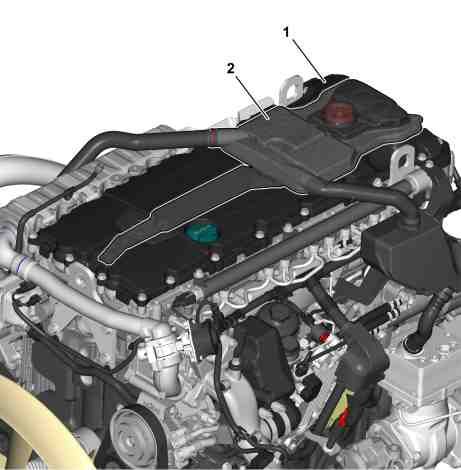
Location
1 | Cylinder head cover |
2 | Oil mist separator |
W01.20-1058-82
A oil mist separator (2) is integrated in the cylinder head cover (1).
Task
The engine oil contained in the blow-by-gases is separated out in the oil mist separator (2) in a number of stages and fed back into the rocker arm housing or into the oil pan.
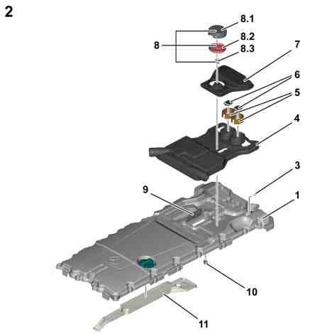
Body
1 | Cylinder head cover |
2 | Oil mist separator |
3 | Oil drain valve |
4 | Oil mist separator housing central part |
5 | Fleece elements |
6 | Leaf springs |
7 | Oil mist separator housing upper part |
8 | Pressure regulator valve |
8.1 | Cover |
8.2 | Diaphragm |
8.3 | Spring |
9 | Nozzle plate (prefilter) |
10 | Check valve |
11 | Vent duct |
W01.20-1059-82

W01.20-1060-78
3 | Oil drain valve | 9 | Nozzle plate (prefilter) | B | Blow-by-gases (with engine oil) | ||
5 | Fleece elements | 11 | Vent duct | C | Blow-by-gases (cleaned) | ||
6 | Leaf springs | 12 | Oil drain duct (from the prefilter - with a check valve (10)) | ||||
8 | Pressure regulator valve | A | Separated out engine oil |
Function
The blow-by-gases (B) pass through an opening on the underside of the cylinder head cover (1) in the oil mist separator (2). The engine oil contained in the blow-by-gases (B) is separated out in the oil mist separator (2) in two stages:
The blow-by-gases (B) are first of all accelerated through the bores in the nozzle plate (9). Immediately after the nozzle plate (9) the accelerated blow-by-gases (B) hit a wall in the oil mist separator-housing central part (4), whereby the engine oil droplets in the blow-by-gases (B) are separated out. The vertically located ribs on the wall improve separation of the engine oil from the blow-by-gases (B) and also ensure that the engine oil can flow away downwards. The separated engine oil (A) again passes over the oil drain duct (12) into the rocker arm housing as soon as sufficient separated engine oil (A) has gathered in order to open the check valve (10) installed in the oil drain duct (12). The check valve (10) also serves to ensure that the blow-by-gases (B) in the rocker arm housing do not find their way over the oil drain duct (12) into the oil mist separator (2).
The fine engine oil droplets which are still contained in the oil mist are subsequently removed with the aid of two impactors and are fed over a duct into the cylinder head and from there back into the oil pan. The impactors consist of two oval mounts on the oil mist separator housing central part (4), two fleece elements (5) and two leaf springs (6). There two bores in the mounts. The blow-by-gases (B) which flow from below into the mounts are accelerated by passing by the bores and impact on the fleece elements (5) located behind. During impact on the fleece elements (5) the refine engine oil droplets are separated out in blow-by-gases (B) and can then flow away downwards. The fleece elements (5) increase the efficiency of oil separation. Since the volumetric flow rate permanently increases with increasing engine rpm, there is a leaf spring (6) on the upper side of each mount. The leaf springs (6) are designed in such a way that they open for higher engine rpms. The blow-by-gases (B) can now also flow through the opened leaf springs (6), are accelerated in the process and again impact on the fleece elements (5) located behind. The engine oil contained in them is separated out and runs away downwards.
If the oil level in the return duct has reached a certain level or the separated out engine oil (A) has reached a certain weight, a check valve in the cylinder head opens and the separated out engine oil (A) runs in to the oil pan. This check valve also prevents the blow-by-gases (B) from passing out of the crankcase directly into the oil mist separator (2).
The cleaned blow-by-gases (C) continue to flow to the pressure regulating valve (8). The pressure regulating valve (8) regulates the pressure in the crankcase and rocker arm housing. If the pressure regulating valve (8) opens, the cleaned blow-by-gases (C) flow into the vent duct (11), which is located on the underside of the cylinder head cover (1). The vent duct (11) opens out into the rocker arm housing, in that the cleaned blow-by-gases (C) are led over a bore in the cylinder head and from there through the coolant manifold, over a hose in the air intake pipe upstream of the turbocharger.
The oil drain valve (3) serves to ensure that the engine oil which precipitates out on the pressure regulating valve (8) can run away into the rocker arm housing when the engine is OFF.