
P01.30-0319-09
1 Cylinder head
2 Camshaft
3 Chain tensioner
4 Engine support
5 Engine mount
11 Collar nut
12 Gasket
13 Exhaust manifold with catalytic converter/ muffler
14 Double open-ended wrench
6 Collar bolt
7 Torx bolt
8 Timing chain
9 Camshaft sprocket
10 Dowel pin
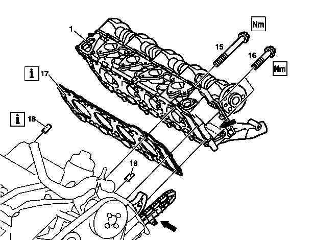
P01.30-0320-06
1 Cylinder head
15 Cylinder head bolt (torx)
16 Torx bolt
17 Cylinder head gasket
18 Fitting sleeve

P03.20-0275-01
Apply sealant (arrows)
| Remove/Install | ||
Danger! | Risk of injury to skin and eyes suffering scalding from contact with hot coolant spray. Risk of poisoning from swallowing coolant. | Do not open cooling system unless coolant temperature is below 90 °C. Open cap slowly and release the pressure. Do not pour coolant into beverage bottles. Wear protective gloves, protective clothing and eye protection. | |
1 | Drain coolant at crankcase | ||
| Notes on coolant | All engines | |
2 | Remove cylinder head cover | ||
3 | Remove ignition coil module | ||
4 | Take off exhaust manifold with catalytic converter/ muffler (13) at cylinder head (1) | Installation: Replace seal (12). Inspect condition of stud bolts in cylinder head, if necessary | |
Replace stud bolts | |||
5 | Remove air shutoff valve | On engines fitted with air pump | |
6 | Remove coolant thermostat | ||
7 | Position piston of cylinder 1 to ignition TDC | The TDC marking on the belt pulley must be aligned with the positioning edge on the timing case cover (arrow). The cams at cylinder 1 are positioned up at an angle. | |
8 | Mark camshaft sprocket (9) and timing chain (8) to each other | Installation: Ensure that the marking of the timing chain (8) is matched with the marking on the camshaft sprocket (9), if necessary | |
Inspect basic position of camshaft, | |||
Set basic position of camshaft | |||
9 | Remove chain tensioner (3) | ||
10 | Take off camshaft sprocket (9) at camshaft (2) and lift off timing chain (8) | Use open-end wrench (14) to counterhold the camshaft (2) Installation: Replace torx bolts (7), use only once. Pay attention to dowel pin (10). | |
| |||
11 | Take off engine mount (5) at engine support (4) | | |
12 | Unscrew torx bolts (16) in chain housing | | |
13 | Slacken cylinder head bolts (15) in stages, remove | Slacken cylinder head bolts (15) in the reverse order of the tightening diagram once engine has cooled down. | |
Tightening diagram of cylinder head bolts | |||
Installation: Oil cylinder head bolts (15) at thread and bolt head contact surface, insert and tighten in stages. | |||
| |||
14 | Inspect cylinder head bolts (15) | ||
15 | Raise cylinder head (1), remove | Installation: Replace cylinder head gasket (17). When fitting on cylinder head (1), insert guide rail pins in cylinder head into the guide rail (arrows). Pay attention to dowel sleeves (18) for locating the cylinder head (1) | |
16 | Clean contact surfaces and threaded holes | Separating surfaces and tapped holes must be free of oil and water. Inspect for cracks and flatness. | |
17 | Apply sealant (arrows) to the web between cylinder head and timing case cover | The sealing compound Loctite 5970 must be processed within 10 minutes. | |
| |||
18 | Install in the reverse order | ||
Danger! | Risk of accident from vehicle starting off by itself when engine running. Risk of injury from bruises and burns if you place your hand into the engine when it is started or when it is running. | Secure vehicle to prevent it moving off. Always wear appropriate work clothing when working on the vehicle. | |
19 | Run engine and inspect for leaks | ||
20 | Inspect cooling system for leaks | Do not pressure-test cooling system until engine has reached operating temperature. The cylinder head gasket is not watertight until the engine has reached operating temperature and the gasket has swollen. |
Inspection data of cylinder head/ cylinder head bolts
Number | Designation | Engine 166.961/ | ||
BE01.30-P-1001-04C | Cylinder head bolt | Thread diameter | M | 10 |
Length (L) when new | mm | 183 | ||
max. length (L) | mm | 186 | ||
Cylinder head
Number | Designation | Engine 166.961/ | ||
BA01.30-P-1001-01E | Bolt of cylinder head to crankcase | 1st stage | Nm | 35 |
2nd stage | ° | 90 | ||
Step 3 | ° | 90 | ||
BA01.30-P-1002-01E | Bolt of cylinder head to timing case cover | Nm | 20 | |
Camshaft
Number | Designation | Engine | ||
BA05.20-P-1001-01C | Bolt of camshaft sprocket to camshaft | 1st stage | Nm | 20 |
Step 2 | | 60 | ||
Exhaust manifold
Number | Designation | Engine 166.961/ | |
BA14.10-P-1001-01C | Collar nut of exhaust manifold with catalytic converter to cylinder head | Nm | 30 |
Engine mounts, engine supports
Number | Designation | Engine 166.961/ | |
BA22.10-P-1005-01G | Bolt of engine carrier to engine mount | Nm | 55 |


112 589 00 25 00
Sealant gun
Double open-end wrench
104 589 01 01 00
Repair materials
Number | Designation | Order number |
BR00.45-Z-1013-01A | Loctite sealant 5970 | A 003 989 98 20 |
Henviste dokumenter
- ah2000n208001a Oplysninger om kølervæske
- ar0120l5014vb
- ar0130p580001gf Tilspændingsskema topbolte
- ar0130p580003gf Topbolte kontrolleres
- ar0510l7800vb
- ar0520l6020vb
- ar0520p6010gf Knastakslernes grundposition kontrolleres
- ar1430p7200gf
- ar1512l1100vb
- ar1512l1100vb
- ar2000l1010va
- ar2000l1142va
- ar2010l2460va
- as0000z000501a Fare for ulykke ved automatisk igangsætning når motoren kører. Fare for personskade på grund af knusning og forbrænding, hvis der arbejdes mens motoren startes eller kører
- as2000z000101a Risiko for skoldningsskader på hud og øjne pga. sprøjtende, varm kølervæske. Risiko for forgiftning ved indtagelse af kølervæske