
D09.41-A007-79
1 | Oil supply connection fitting | 9 | Rail | 18 | Electrical wiring harness | ||
2 | Fuel filter | 13 | Leak oil line | 19 | Screw | ||
3 | Bracket | 14 | Electrical connectors | 20 | Lifting eye | ||
4 | Screw | 15 | Electrical connector | 21 | Bracket | ||
8 | Vacuum line |

D09.41-A008-79
10 | High pressure pipe | 23 | Screw | 26 | Engine suspension lug | ||
11 | Screw | 24 | Bolts | 27 | Sealing ring | ||
12 | Nut | 25 | Charge air distributor | 28 | Seal | ||
22 | Bracket |
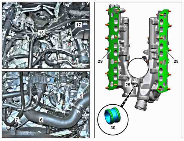
5 | Screw |
6 | Coolant hose |
7 | Coolant hose |
16 | Electrical connectors |
17 | Electrical connector |
25 | Charge air distributor |
29 | Seal |
30 | Connection piece |
D09.41-A009-76
Danger | Risk of explosion caused by fuel igniting, risk of poisoning caused by inhaling and swallowing fuel as well as risk of injury to eyes and skin caused by contactwith fuel. | No fires, sparks, open flames or smoking. Pour fuels into suitable and appropriately marked containers only. | |
Warning | Risk of injury to skin and eyes suffering scalding from contact with hot coolantspray. Risk of poisoning from swallowing coolant. | Do not open cooling system unless coolant temperature is below 90 °C. Open cap slowly and release the pressure. Do not pour coolant into beverage containers. | |
Caution | Risk of injury caused by scraping or cutting body parts on sharp vehicle parts | Always wear protective gloves when working on or near sharp and non-deburred vehicle parts. | |
Caution | Risk of injury to skin and eyes due to handling of engine oil. Risk of poisoning caused by swallowing engine oil | Wear protective gloves, protective clothing and safety glasses. | |
Topical note | Information on preventing damage to electronic components due to electrostatic discharge | ||
Topical note | Notes on avoiding damage through contamination and foreign objects | ||
Notes about Common-Rail components | |||
| Remove | ||
1 | Drain off coolant. | ||
2 | Remove oil supply connection fitting (1) of exhaust gas turbocharger. | ||
3 | Remove fuel filter (2). | ||
4 | Remove the bracket (3). | To do this, remove screw (4). | |
5 | Remove screw (5). | ||
6 | Remove coolant hose (6) from coolant thermostat housing. | ||
Plug openings. | |||
Set of protective caps | |||
7 | Remove coolant hose (7). | Plug openings. | |
Record plug | |||
Hose clamp pliers | |||
8 | Remove vacuum line (8). | To do so, disassemble and remove vacuum line (8) on vacuum pump and on brake booster. Plug openings. | |
Record plug | |||
9 | Remove rail (9) on right cylinder head. | ||
10 | Remove high-pressure line (10). | For this purpose, remove screws (11) and nut (12). Close off connection on rail. | |
Open wrench insert, (18 mm) | |||
Record plug | |||
11 | Remove leak oil line (13) at fuel injectors. | ||
12 | Remove leak oil line (13) from coolant thermostat housing and place outside working area. | ||
13 | Disconnect electrical connectors (14) for fuel injectors. | ||
14 | Disconnect electrical connector (15) on camshaft position sensor. | ||
15 | Disconnect electrical connectors (16) of glow plugs. | Pliers | |
16 | Disconnect electrical connector (17) for coolant temperature sensor. | ||
17 | Remove electrical wiring harness (18). | Proceed by first removing the screws (19). | |
18 | Place electrical wiring harness (18) outside the working area. | ||
19 | Remove engine lifting lug (20). | To do this, unscrew screws. | |
20 | Remove bracket (21) from charge-air distributor (25). | To do this, unscrew screws. | |
21 | Remove bracket (22) for fuel filter (2). | Remove screw (23) to do this. | |
22 | Remove two screws from charge-air distributor (25) in the area below the bracket (22). | Set of flexible head wrenches | |
23 | Tighten the loosened screw in bracket (22). | Bolt, hose clamp cage to fuel filter | |
24 | Reinstall bracket (22) for fuel filter (2). | To do this, screw in the screws (11, 23). | |
Screw, high-pressure line retaining clamp to cylinder head cover/charge-air distributor | |||
Bolt, clamp for fuel filter to charge-air distributor | |||
25 | Remove screws (24). | ||
26 | Remove remaining screws on charge-air distributor (25). | In the process, remove engine lifting lug (26). Note down the assignment of the screws due to the differing shank lengths. | |
Set of flexible head wrenches | |||
27 | Remove charge-air distributor (2). | ||
28 | Remove sealing ring (27). | Dispose of sealing ring (27). | |
29 | Remove seal (28). | Dispose of seal (28). | |
30 | Remove seals (29). | Dispose of seals (29). | |
31 | Remove bracket (22) for fuel filter (2). | To do so, remove the screws (11, 23). | |
32 | Remove connection piece (30). | To this end, disassemble sections of the charge-air distributor (25) from one another. Dispose of connection piece (30). | |
| Clean | ||
33 | Clean sealing surfaces on cylinder heads and on mixer housing with a lint-free cloth. | ||
34 | Clean sealing surfaces on charge-air distributor (25). | When reusing the charge-air distributor (25). | |
Assembly cleaner | |||
| Install | ||
35 | Transfer the coolant thermostat housing. | When replacing charge-air distributor (25). | |
36 | Transfer coolant temperature sensor. | When replacing charge-air distributor (25). | |
37 | Assemble sections of charge-air distributor (25). | Install new connection piece (30). | |
38 | Install bracket (22) for fuel filter (2). | To do this, screw in the screws (11, 23). | |
Screw, high-pressure line retaining clamp to cylinder head cover/charge-air distributor | |||
Bolt, clamp for fuel filter to charge-air distributor | |||
39 | Mount new seals (29). | Clip seals (29) onto charge-air distributor (25). | |
40 | Install new seal (28). | ||
41 | Install new sealing ring (27). | ||
42 | Install and align charge-air distributor (25). | ||
43 | Screw in screws of charge-air distributor (25) according to the tightening procedure. | ||
In the process, engine lifting lug (26) is installed and bracket (22) is removed. Remember that the shafts vary in length. | |||
WIS Service Media | |||
Screw/bolt, charge air distributor to cylinder head | |||
Set of flexible head wrenches | |||
44 | Screw in screws (24). | Screw/bolt, mixing chamber to charge air distributor | |
45 | Install bracket (22) for fuel filter (2) and fasten using screw (23). | Tighten screw (23) slightly by hand. | |
46 | Install bracket (21) on charge-air distributor (25). | For this purpose, screw in screws. | |
Bolt, bracket to charge-air distributor | |||
47 | Install engine lifting lug (20). | For this purpose, screw in screws. | |
48 | Position electrical wiring harness (18) in the working area. | ||
49 | Connect electrical connector (17) of coolant temperature sensor. | ||
50 | Connect electrical connectors (16) of glow plugs. | ||
51 | Connect electrical connector (15) of camshaft position sensor. | ||
52 | Connect electrical connectors (14) of fuel injectors. | ||
53 | Fasten electrical wiring harness (18) in the working area. | To do so, screw in screws (19). | |
54 | Position leak oil line (13) in the working area. | ||
55 | Attach leak oil line (13) to fuel injectors. | ||
56 | Attach leak oil line (13) to coolant thermostat housing. | ||
57 | Install high-pressure line (10). | ||
Topical note | Notes on threaded connections fastened using a tightening angle-based tightening process | ||
Note on calculation of tightening torque when using insertion or socket tools with various effective lengths | |||
| |||
Union nut, rail high-pressure line to rail | |||
Open wrench insert, (18 mm) | |||
Record plug | |||
58 | Screw in screws (11). | Screw, high-pressure line retaining clamp to cylinder head cover/charge-air distributor | |
59 | Tighten screw (23). | Bolt, clamp for fuel filter to charge-air distributor | |
60 | Install rail (9) on right cylinder head. | ||
61 | Install vacuum line (8). | To do so, attach vacuum line (8) to vacuum pump and brake booster. Check seal on brake booster for damage. | |
Record plug | |||
If the seal is damaged. | |||
| |||
Replace seal. | |||
62 | Attach coolant hose (7). | Record plug | |
Hose clamp pliers | |||
63 | Attach coolant hose (6) to coolant thermostat housing. | ||
Set of protective caps | |||
64 | Screw in screw (5) . | ||
65 | Install bracket (3). | Screw in screw (4) to do this. | |
66 | Install fuel filter (2). | ||
67 | Install oil supply connection fitting (1) of exhaust gas turbocharger. | ||
68 | Fill in coolant. | ||
| Check | ||
Warning | Risk of accident from vehicle starting off by itself when engine running. Risk of injury (bruises and burns) resulting from working on the engine while it is being started or when it is running. | Secure vehicle to prevent it from starting off by itself. Wear closed and snug-fitting work clothes. Do not touch hot or rotating parts. | |
69 | Check for leaktightness when engine is running. | Visual inspection only. |


611 589 00 37 00
Pliers
454 589 00 37 00
Hose clamp pliers
001 589 81 09 00
Set of flexible head wrenches
000 589 30 01 00
Open wrench insert, (18 mm)


129 589 00 91 00
Record plug
001 589 02 91 00
Set of protective caps
Powiązane dokumenty
- ah0000p001501cw Wskazówka dotycząca obliczania momentu dokręcania przy stosowaniu narzędzi o różnej długości dźwigni
- ah0000p002001a Wskazówki dotyczące połączeń śrubowych tworzonych według kąta dokręcenia
- ah0000p500001a Wskazówki dotyczące zapobiegania uszkodzeniom na skutek zabrudzeń i ciał obcych
- ah0716p000201tx Wskazówki dotyczące zespołów układu Common-Rail
- ah5400p000101a Wskazówki dotyczące zapobiegania uszkodzeniom elementów elektronicznych na skutek rozładowania potencjału elektrostatycznego
- ar0703d1012tsv
- ar0703d9110tsv
- ar0940d6023tsv
- ar0941d868301tsv
- ar1560d2712tsv
- ar2000d1142tsr
- ar2010d2461tsv
- ar2020s386515s Odłączanie, podłączanie elastycznego przewodu płynu chłodzącego do obudowy termostatu układu chłodzenia
- ar4720d5510tsv
- as0000z000501a Niebezpieczeństwo wypadku na skutek samoczynnego ruszenia przy pracującym silniku. Niebezpieczeństwo obrażeń na skutek zmiażdżenia lub poparzenia przy wykonywaniu czynności podczas rozruchu lub przy pracującym silniku.
- as0000z001701a Niebezpieczeństwo obrażeńo elementy pojazdu o ostrych krawędziach.
- as1800z000101a Niebezpieczeństwo obrażeń skóry i oczu podczas kontaktu z olejem silnikowym. Niebezpieczeństwo zatrucia wskutek połknięcia oleju silnikowego
- as2000z000101a Niebezpieczeństwo zranienia skóry i oczu przez poparzenie wytryskującym, gorącympłynem chłodzącym. Niebezpieczeństwo zatrucia na skutek połknięcia płynu chłodzącego
- as4700z000101a Niebezpieczeństwo wybuchu wskutek zapalenia, niebezpieczeństwo zatrucia wskutek wdychania i połknięcia paliwa oraz niebezpieczeństwo obrażeń wskutek kontaktu skóry i oczu z paliwem.