
S09.00-4509-79
Shown without code MT2 (emissions class Euro 6d-TEMP N1 GR.III/N2) |
B4/14 | Rail pressure sensor | Y76 | Fuel injectors | |
B11/17 | Coolant temperature sensor | Y77/11 | Boost pressure control pressure transducer | |
B17 | Charge air temperature sensor upstream of throttle valve | A | Mercedes-Benz | |
B19/11 | Temperature sensor upstream of turbocharger | B | Nissan | |
B60/3 | Exhaust back pressure sensor | C | Default | |
B70/2 | Crankshaft Hall sensor | D | Optional | |
N3/33 | CDI control unit |
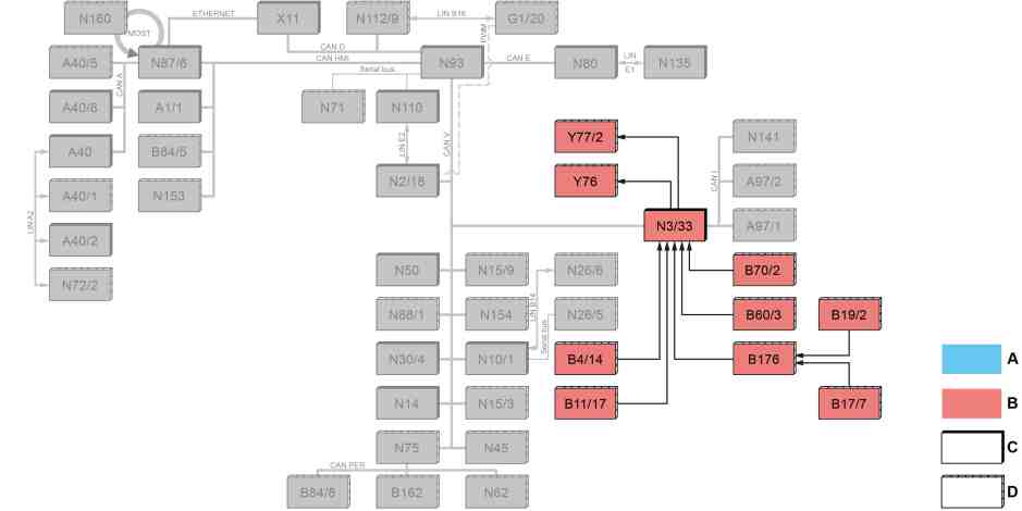
S09.00-A007-79
Shown with code MT2 (emissions class Euro 6d-TEMP N1 GR.III/N2) |
B4/14 | Rail pressure sensor | N3/33 | CDI control unit | |
B11/17 | Coolant temperature sensor | Y76 | Fuel injectors | |
B17/7 | Exhaust temperature sensor | Y77/2 | Exhaust gas turbocharger actuator | |
B19/2 | Temperature sensor upstream of turbocharger | A | Mercedes-Benz | |
B60/3 | Exhaust back pressure sensor | B | Nissan | |
B70/2 | Crankshaft Hall sensor | C | Default | |
B176 | Exhaust gas temperature sensor unit | D | Optional |
Function requirements for charging - general
Engine running.
Forced induction, general
The cylinder charging efficiency is improved as a result of forced induction. As a result, the engine torque and power output are boosted.
During forced induction, the flow energy of the exhaust gases is used to drive the ATL.
The ATL suctions in fresh air through the air filter on the compactor inlet and feeds it through the compressor outlet into the charge air pipe upstream of the charge air cooler. The high number of revolutions of the compressor wheel and the resulting high flow volume compacts the air in the charge air pipe. The compacting heats the charge air, which now flows through the charge air pipe to the charge air cooler. This cools off the charge air and feeds it through to the cylinder head.
Charging is regulated by the boost pressure control. The boost pressure is regulated by the CDI control unit (N3/33) among other things dependent on the following sensors and signals:
Rail pressure sensor (B4/14)
Coolant temperature sensor (B11/17)
Charge air temperature sensor upstream of the throttle valve (B17) (without CODE MT2 (emissions class Euro 6d-TEMP N1 GR.III/N2))
Exhaust gas temperature sensor (B17/7) above sensor unit of the exhaust gas temperature sensor (B176) (with code MT2 (emissions class Euro 6d-TEMP N1 GR.III/N2))
Temperature sensor upstream of exhaust gas turbocharger (B19/11) (without code MT2 (emissions class Euro 6d-TEMP N1 GR.III/N2))
Temperature sensor upstream of the exhaust gas turbocharger (B19/2) above sensor unit of the exhaust gas temperature sensor (B176) (with code MT2 (emissions class Euro 6d-TEMP N1 GR.III/N2))
Exhaust back pressure sensor (B60/3)
Crankshaft Hall sensor (B70/2)
Atmospheric pressure sensor in CDI control unit (N3/33)
Injection period of fuel injectors (Y76)
Function sequence for boost pressure control
The boost pressure control occurs via the boost pressure control pressure transducer (Y77/11) and exhaust gas turbocharger actuator (Y77/2) (with code MT2 (emissions class Euro 6d-TEMP N1 GR.III/N2)); this is actuated by the CDI control unit depending on the characteristics map (N3/33) and the load.
In this way the position of the guide vane in the ATL is adjusted. The guide vanes modify the flow cross-section through which the exhaust gas flows to the turbine. The guide vanes thus match the gas pressure present at the turbine to the required boost pressure.
The number of revolutions of the exhaust gas turbocharger is used to determine the amount of pre-compressed air and thus the boost pressure. The boost pressure is constantly monitored by the charge air temperature sensor upstream of the throttle valve (B17) (without code MT2 (emissions class Euro 6d-TEMP N1 GR.III/N2)) and passed on to the CDI control unit (N3/33). In wide open throttle operation, maximum boost pressure builds up.
As protection from the overload of the exhaust gas turbocharger, the exhaust gas temperature is monitored by the temperature sensor upstream of the exhaust gas turbocharger and the exhaust gas pressure is monitored by the exhaust back pressure sensor (B60/3) of the CDI control unit (N3/33). The boost pressure is reduced if there is any risk of thermal or mechanical overload.
Referenced documents
- gf0716s9997pd Overview of system components for common rail diesel injection (CDI)