AR49.20-W-1001-02A | Modify pressure line with connection on exhaust aftertreatment unit | ||
Caution | Risk of injury caused by scraping or cutting body parts on sharp vehicle parts | Always wear protective gloves when working on or near sharp and non-deburred vehicle parts. | |
General information and guidelines for welding on the exhaust aftertreatment unit |

1 | Saw off pressure line (1) near to the union nut (4). |
2 | Loosen union nut (2) and press away pressure line (1) to the side. |
W49.20-1165-11
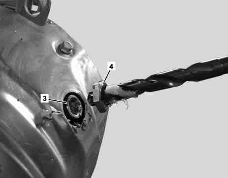
3 | Drill pressure line connection (3) straight in so deep that the union nut (4) is completely removed and the repair adapter (5) can later be inserted up to its collar. |
Ensure that neither grease nor chips can find its way into the EATU. |
Coat the drill bit with grease so that the chips stick to it and cannot find their way into the EATU. Use various drill bit with ever larger diameters one after the other. Beginning with Ø 10 mm to about Ø 14.5 mm. Start with 1 mm steps - later with 0.5 mm steps. |
W49.20-1166-11

4 | Clean pressure line connection (3). |
5 | Place the repair adapter (5) as shown in the pressure line connection (3). |
The repair adapter (5) must lie with its collar on the pressure line connection (3). |
W49.20-1167-11

6 | Weld the repair adapter (5) into the pressure line connection (3) gas-tight. |
W49.20-1188-11

7 | Coat the union nut (7) thinly with high-temperature grease. |
8 | Introduce the new pressure line (6) with a cutting ring (8) and union nut (7) into the repair adapter (5). |
9 | Tighten the union nut (7) slightly. |
The new pressure line (6) must still remain rotatable. |
10 | Align the remaining pressure line (1) and the new pressure line (6) together. |
11 | Cut to length the new pressure line (1) and the remaining pressure line (6). |
There are different variants according to the EATU. For this reason the pressure lines (6) and (1) must be cut to a length as required. For the following operation step there should be as little bridging as possible with the hose piece (9). If necessary the pressure lines (6) and (1) must be bent back somewhat. |
W49.20-1169-11

12 | Connect both pressure lines (1, 6) with the hose piece (9) and the hose clamps (10). |
One must ensure that the hose piece (9) is not kinked. |
The hose piece (9) should be shortened in such a way that the pressure lines (1, 6) jut out on either side by about 3 cm in the hose piece (9). |
W49.20-1170-11