GF54.30-P-2014RT | Indicator lamp test and engine running detection, function | 19.6.06 |
MODEL 251.1 /0 up to Model Year 8
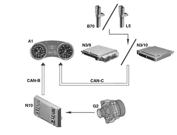
P54.30-8334-06
Networking
A1 Instrument cluster
B70 Crankshaft Hall sensor
G2 Alternator
L5 Crankshaft position sensor
N3/9 CDI control unit
N3/10 ME control unit
N10 Front SAM ECU
CAN B interior CAN.
CAN-C Engine compartment CAN
Indicator lamp test
An indicator lamp test is performed via the instrument cluster at "circuit 15 ON". In the process all the indicator and warning lamps (where fitted as per equipment variants and national variants) are actuated, except:
left turn signal indicator lamp (A1e1),
right turn signal indicator lamp (A1e2), and
High beam indicator lamp (A1e3),
Seat belt warning lamp (A1e9),
Preglow indicator lamp (A1e16).
The indicator lamp test only takes place as long as "circuit 61" is "LOW" level (circuit 61 < 9 V) and the alternator is not yet operating as well as the engine speed is less than 200 rpm.
If no malfunctions are present the indicator lamps will go out as soon as the engine starts to run.
-----------------------------------------------------------------------------------------
Engine running recognition "circuit 61e"
The instrument cluster combines the CAN messages
"circuit 61" and "engine speed" for the CAN-message "circuit 61e" engine running detection.
This CAN message can have either a "HIGH" or "LOW" status.
It is "LOW" when "Terminal 61" is "LOW" and the engine speed is less than 200 rpm.
The CAN message is "HIGH" if the engine speed is higher than 200 rpm.
The signal "circuit 61e" is placed on the engine compartment CAN as a CAN message from the instrument cluster and is thus available to the control units of this bus system which require this CAN message.
-----------------------------------------------------------------------------------------
Networking
The following CAN messages are required:
"Circuit 61" (alternator check)
The signal "circuit 61" from the alternator (alternator check) is read in by the front SAM control unit. This then relays the message "Terminal 61 HIGH" (alternator operating) or "Terminal 61 LOW" (alternator not operating) onto the interior compartment CAN.
Engine speed
The pulses from the crankshaft position sensor (engine 113, 156 only) or from the crankshaft Hall sensor (engine 272, 273, 642 only) are read in by the ME-SFI control unit or CDI control unit.
The control units place the engine speed message on the CAN engine compartment.
The instrument cluster receives these messages and evaluates them as described above.
The same CAN messages are used for the charge indicator warning "BATTERY/ALTERNATOR VISIT WORKSHOP." This message appears in the multifunction display (A1p13) if "Circuit 61" is "LOW" and the engine speed is higher than 200 rpm.
The following chart recapitulates the interrelationships portrayed in the above section.
Terminal 61 | Engine speed | Term. 61e | Instrument cluster |
low (< 4.5 V) | too low | LOW | Indicator lamp test |
low (< 4.5 V) | o.k. | HIGH | "BATTERY/ GENERATOR - GO TO GARAGE |
high (> 9 V) | too low | HIGH | - |
high (> 9 V) | o.k. | HIGH | - |
HIGH (< 4.5 V) | Signal fault | LOW | Indicator lamp test |
high (> 9 V) | Signal fault | HIGH | - |
Referenced documents
- gf5430p2013rt Output acoustic warning messages, function