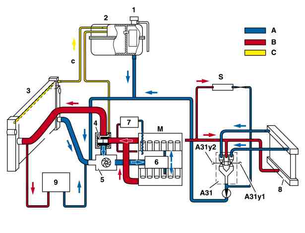
P20.00-2043-76
Coolant circuit diagram model 220, 215 with engine 137
1 2-stage cap
2 Coolant expansion reservoir with silica gel tank
3 Radiator
4 Coolant thermostat (position engine at normal operating temperature)
5 Coolant pump
6 Oil-water heat exchanger to oil filter
7 Coolant of cooled generator
8 Heating system heat exchanger
9 Additional coolant cooler in right wheelhousing
A31 Heating system delivery unit
A31y2 Left duovalve
A31y2 Right duovalve
A Coolant return flow
B Coolant feed
C Vent line
Engine cooling
All the components positioned in direction of travel ahead of the engine are combined in a cooling module.
The cooling module includes:
a 16 mm flat tube condenser with integrated steering oil cooler in the upper half
a coolant cooler with integrated transmission oil heat exchanger
an electric suction fan
Radiator area sealing
an ABC (active body control) oil cooler
An additional coolant cooler is housed in the front right wheelhousing.
The coolant hoses between cooling module and engine are connected with a quick-coupling system.
The overflow tank, fitted previously for avoiding a loss of coolant when the engine is switched off, is discontinued as the loss of coolant as a result of the formation of vapor bubbles during reheating, is avoided by means of a two-stage pressure valve in the coolant system cap.
The engine fan with viscous clutch, and the electric additional fan, used previously are replaced on engine 137 with a new design of EC (electrically commutated, brushless or carbonless) suction fan with a large blower wheel of 520 mm. The fan speed of the EC suction fan is steplessly electronically controlled in line with demand by the engine control module, on the bases of the
coolant temperature and the air conditioning system