GF07.05-P-3105MOR | Component description for air divert switchover valve | 13.11.08 |
ENGINE 275.9 in MODEL 230.4 as of model year 2009
/ AEJ 08 model refinement package

P07.61-2706-01
View of engine from rear right
5/2 Charge air cooler for right cylinder bank
N92/1 ECI ignition module, right cylinder bank
Y32 Air pump switchover valve
Y101 Divert air switchover valve
Location
The bypass air switchover valve located at the rear of the RH cylinder head.
Observe risk of mixing up with air pump switchover valve.
Task
The bypass air switchover valve actuates the blow-off valve to the turbocharger using a vacuum.

P07.10-0308-81
Design
1 Aeration connection
2 Vacuum pressure supply connection
3 Connection to the blow-off valves
a Armature disk
b Return spring
c Housing
d Solenoid
e Electrical connection
f Rubber seal
P14.30-2114-75
Function
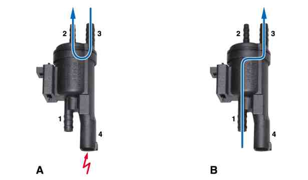
1 Aeration connector (via intake manifold)
2 Vacuum supply connector
(from vacuum reservoir)
3 Connection to the blow-off valves
4 Electrical connection
A Bypass air switchover valve energized (blow-off valves have a vacuum applied to them)
B Bypass air switchover valve deenergized
(blow-off valves ventilated)
The bypass air switchover valve is directly actuated for a crossover of load to deceleration mode by the ME-SFI [ME] control unit (N3/10) by means of a ground signal.
The voltage supply takes place from "circuit 87 M2".
When energized, the armature disk (a) is tightened down by the solenoid (d) and the rubber seal (f) closes connection 1. The connection between connections 2 and 3 is released and the vacuum from the vacuum reservoir is dispersed in the blow-off valves.
In the deenergized state, the connection is restored between connections 1 and 3, which causes the blow-off valves to be ventilated again (via connection 3).