
G27.10-3119-78
1 | Propeller shaft | 7 | Screw | 13 | Rear transmission carrier | ||
2 | Coolant hose | 8 | Screw | 14 | Clip | ||
3 | Coolant pipe | 9 | Bracket | 15 | Compressor line | ||
4 | Electrical connector | 10 | Cross strut | 16 | Nut | ||
5 | Bracket | 11 | Front transmission carrier | ||||
6 | Screw | 12 | Center transmission carrier |

17 | Screw |
18 | Screw |
19 | Power take-off |
20 | Filler pipe |
21 | Coolant hose |
22 | Bracket |
23 | Solenoid valve unit |
24 | Electrical connector |
G27.10-3120-76

25 | Timing case |
26 | Cap |
27 | Wooden support |
28 | Ring gear carrier |
29 | Screw |
Pfeil A | Access opening |
G27.10-3121-74

G27.10-3124-78
13 | Rear transmission carrier | 32 | Transmission bracket | |
30 | Vent line | 33 | Torque converter | |
31 | Screw | 34 | Guide pin |
| Remove/install | ||
1 | Remove body | See information from vehicle manufacturer. | |
2 | Drain coolant | ||
| |||
3 | Remove exhaust pipe between valve fitting and rear muffler | Clamp, flexible exhaust pipe to valve fitting | |
4 | Disconnect electrical connection (4) | ||
5 | Remove drive shaft (1) | Nut, propeller shaft to output flange | |
Nut, drive shaft to drive flange | |||
6 | Remove bracket (5) between coolant pipe (3) and transmission | ||
7 | Detach coolant hose (2) from transmission and collect escaping coolant | ||
8 | Completely remove bracket (9) together with cross strut (10) | ||
9 | Remove clamp (14) from compressor line (15) | ||
10 | Unscrew nut (16) from compressor line (15) | ||
11 | Remove filler pipe (20) and seal bore on transmission using lint-free rag | ||
12 | Detach bracket (22) from cross member and place solenoid valve unit (23) to one side | ||
13 | Detach coolant hose (21) and bracket from coolant pipe on transmission, and collect escaping coolant | The bracket for the coolant pipe is located in the vicinity of the power take-off (19). | |
14 | Detach adaptation or connections from power take-off (19) | With code NU4 (PTO automatic transmission, 8 o'clock, low speed, pump) | |
See information from vehicle manufacturer. | |||
15 | Disconnect electrical connector (24) from power take-off (19) | With code NU4 (PTO automatic transmission, 8 o'clock, low speed, pump) | |
16 | Remove screws (6, 18) | Front transmission carrier to engine mount | |
17 | Detach radiator unit at top and tilt forward | ||
For the following operation steps, the transmission must be raised along with the engine, to do so, the distance between the engine and the radiator unit must be increased. | |||
18 | Mount crane gripper chain to rear transmission carrier (13) | ||
19 | Raise transmission and engine using crane until the bolts (7, 8) can be removed | | |
20 | Remove bolts (7, 8, 17) | Installation: The bolts (8) on the right side are countersunk bolts and they have to be installed again at the same position. | |
Front transmission carrier to engine timing case | |||
21 | Disconnect center transmission carrier (12) from rear transmission carrier (13) | Center transmission carrier to rear transmission carrier | |
22 | Remove center transmission carrier (12) together with front transmission carrier (11) | ||
23 | Lower transmission and engine using crane to horizontal position | ||
24 | Position a jack stand with suitable wooden support (27) under the timing case (25) | Position wooden support as close to front bar of timing case (25). | |
25 | Lower transmission and engine using crane until the timing case (25) makes contact with the wooden support (27), do not relieve load on crane or chain | ||
26 | Place suitable wooden support onto plate-type vehicle jack and prop-up transmission using plate-type vehicle jack | | |
27 | Remove crane and pull chain from rear transmission carrier (13) | ||
28 | Mount transmission carrier (32), as shown, onto transmission | | |
Transmission bracket | |||
29 | Hook pull chain, as shown, into eyelet of transmission carrier (32) | ||
30 | Raise transmission using pull chain and crane far enough to tension the pull chain | ||
31 | Lower plate vehicle jack | ||
32 | Remove bracket and cover in front of access opening (arrow A) | Use a screwdriver to pry off the cover in front of the access opening (arrow A). | |
Installation: Coat sealing surface between timing case (25) and cover with sealant. | |||
Sealant, Loctite 5970, 50 ml | |||
33 | Attach turning device for engine | ||
Installation: Coat sealing surface between timing case (25) and cap (26) with sealant. | |||
Inspection hole cap to timing case | |||
Sealant, Loctite 5970, 50 ml | |||
Turning device | |||
34 | Gradually turn the turning device and remove accessible bolts (29) around circumference of ring gear carrier (28) | Installation: Remove guide pin (34), screw in first bolt (29) and tighten finger-tight. | |
Bolt, torque converter to drive plate | |||
35 | Detach vent line (30) from transmission | Installation: Replace seal. | |
36 | Mark installation position of brackets fastened in place with the bolts (31) | ||
37 | Remove bolts (31) | Bolt, transmission to timing case | |
38 | Remove transmission | ||
| Guide pin used to install the transmission | ||
Installation: Screw guide pin (34) into lowest threaded hole of torque converter (33). | |||
39 | Place transmission onto suitable base and remove transmission carrier (32) from transmission | Installation: | |
Installation: Coat contact surface between guide pin on torque converter (33) and clutch plate on engine with long-life grease. | |||
Long-life grease | |||
Loctite 5203 sealant | |||
Transmission bracket | |||
40 | Install in the reverse order | ||
41 | Fill transmission with transmission fluid | Only when installing a new transmission or when the oil was drained. | |
| |||
42 | Check and correct oil level | ||
| |||
43 | Mount diagnostic system and read out, delete fault memory | ||
| |||
Stored faults, which may result from wires being disconnected or from simulation during assembly or testing, have to be processed and erased in the fault memories after completing the work. | |||
44 | Reinitialize the control unit using the diagnostic system | Only when installing a new transmission. | |
In the Actuations menu, perform "New initialization of the adapted parameters". | |||
45 | Detach diagnostic system | ||
46 | Conduct a road test | Note the following when installing a new transmission: | |
Update Vehicle Documentation (VeDoc) | |||
47 | Document transmission number in VeDoc | Only when installing a new transmission. |
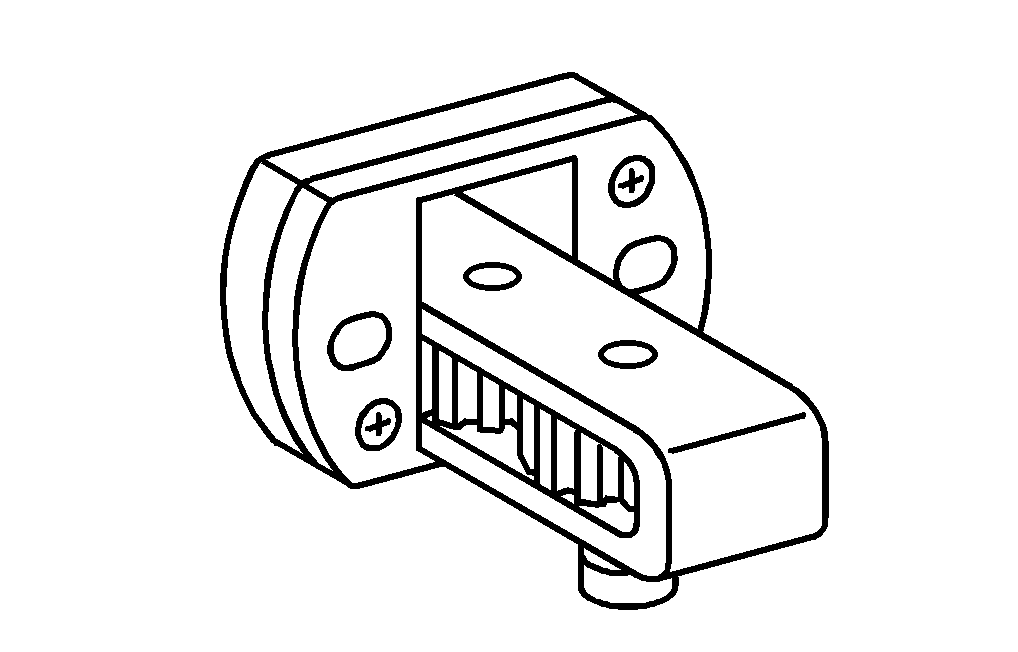

904 589 04 63 00
Turning device
437 589 00 40 00
Transmission bracket
Referenced documents
- ad0000g200004b Connect STAR DIAGNOSIS and read out fault memory
- ap2000g2080f Replace coolant
- ap2700g2702fa Automatic transmission fluid and oil filter change
- ap2700g2710fa Automatic transmission - Check/correct oil level
- ar0330g160003b Attach/detach cranking/blocking device for engine
- ar2020g387101f Unfasten/fasten radiator unit for assembly operations
- wf5850a271001la Guide pin used to install the transmission