
B26.50-0307-09
1 Counter shaft bearing cap (front)
2 Counter shaft brake cover
3 Drive shaft cover
4 Drive shaft bearing cap (front)
5 Piston
6 Control rod
7 Front housing
8 Sliding shoes
9 Splitter group coupling fork
10 Oil tube
11 Counter shaft
12 Counter shaft bearing cap (rear)
13 Bolt
14 Oil pump
15 Flange
16 Coupling fork pins
17 Rear housing
18 Main shaft bearing cap (rear)
19 Main shaft (with gear shift unit)
20 Synchronizing cone with synchronizing ring and ring spring
21 Drive shaft
22 SSplitter group fork pin
23 Bolt
24 Gear shift control
25 Reverse gear axle
26 Fastening plate
27 Rear cover
| Assemble | ||
1 | Assemble the counter shaft (11) | ||
2 | Assemble the drive shaft (21) | ||
3 | Install the main shaft (19) | ||
4 | Assemble the radial seal and the guide bushing of the splitter group control rod | ||
Mandrel | |||
Synthetic grease | |||
5 | Install the control rod (6) and splitter group's control piston (5) | The coupling fork of the splitter group (9) must engage in the control rod's recess (6). | |
6 | Assemble the splitter group's coupling fork pin (22) | Put quick drying adhesive on the splitter group's engaging fork pin (22). | |
| |||
7 | Assemble the drive shaft (4) bearing cap and the counter shaft (1) bearing cap in the front housing (7) | Put multi-use grease on the tapered roller bearing caps of the drive shaft (4) and counter shaft (1). | |
Use an appropriate mandrel. | |||
8 | Assemble the drive shaft (3) bearing cap in the front housing (7) | Tighten the bolts manually. | |
9 | Assemble the drive shaft (21) and install the synchronizing cone with the synchronizing ring and the ring spring (20) in the front housing (7) | Check the wear limit between the synchronizing cone and the coupling sleeve (20). | |
Oil the synchronizing cone with the synchronizing ring and the ring spring (20) | |||
10 | Assemble the gear control unit (24) | ||
11 | Assemble the control bars and put the guide plate of the control bars in the front housing (7) | | |
12 | Assemble the main shaft (19) with the counter shaft (11) in the gearbox front housing (7) | ||
Immobilizer device | |||
13 | Assemble the coupling forks with the sliding shoes in the main shaft (19) | ||
14 | Assemble the oil tube (10) | Pay attention to the correct position for the assembly of the oil tube (10). | |
15 | Put the guide pins in the front housing (7) | Only when they have been removed. | |
| Guide pin | ||
16 | Put he centering mandrel in the oil tube (10) | Centering mandrel | |
17 | Assemble the main shaft (18) bearing cap and the counter shaft (12) bearing cap in the rear housing (17) | Put multi-use grease on the tapered roller bearings of the counter shaft (12) and main shaft (18). | |
Use an appropriate mandrel. | |||
18 | Put the reverse speed gear (29) in the rear housing (17) | Move laterally the reverse speed gear (29) in the rear housing (17) | |
19 | Fit the rear housing (17) on the front housing (7) | ||
Put sealing compound on the sealing surfaces. | |||
20 | Put the bolts (13) that fasten the rear housing (17) to the front housing (7) | Pay attention to the different lengths of the fastening bolts (13). | |
| |||
21 | Install the fork pins (16) | Put a chemical bond on the fork pins (16). | |
| |||
22 | Assemble the reverse speed gear (25) put the fastening plate (26) and put the bolt (23) | ||
| |||
23 | Determine the compensation washers for the drive shaft (21) and counter shaft (11) | ||
| |||
Torque wrench | |||
Tensioning plates | |||
24 | Assemble the drive shaft (3) cover with the determined washer | ||
| |||
25 | Assemble the drive shaft (2) cover with the determined washer | The brake blades oil grooves must be aligned. | |
| |||
26 | Position the gearbox in the horizontal position | ||
27 | Determine the compensation washer for the splitter group control piston | ||
28 | Remove the control rod with the assembly tool | ||
| Assembly tool for the installation of the splitter group control rod | ||
29 | Assemble the double groove seal and the control piston | Put synthetic grease on the double groove seal. | |
Lock the control piston with a quick drying bond. | |||
| |||
Socket | |||
30 | Determine the compensation washer for the splitter group control cylinder | ||
Inner puller | |||
Counter support | |||
Put synthetic grease on the sealing rings. | |||
30.1 | Assemble the gearbox rear cover (27) | Only for vehicles without code B10 Voith retarder 115 | |
30.2 | Assemble the retarder | Only vehicles with code B10 Voith Retarder 115 | |
31 | Assemble the gearbox sensors | ||
32 | Assemble the gear shift module | ||
| |||
33 | Assemble the gear selection cylinder | ||
| |||
34 | Assemble the compressed air tubes and the support in the gearbox | ||
With the “VOSS 230” air connection system. | |||
With the “VOSS 232” air connection system (NG 8, 12) or “SCHAFER SDF” (NG 6). | |||
35 | Assemble the gear shift control unit | ||
| |||
36 | Install the output flange | ||
| |||
37 | Assemble the connectors' electric wires in the sensors and supports | ||
38 | Assemble the clutch fork | | |
39 | Install the gearbox | ||
40 | Supply the gearbox with oil | ||
|
Splitter group
Número | Denominação | Gearboxes 714.183 | |||
BE26.35-B-1002-01B | Adjusting measurement of the split group shift cylinder | mm | 0,4...0,5 | ||
Gear assembly
Número | Denominação | Gearbox 714.183 | |||
BE26.50-B-1004-01G | Wear limit between the synchromesh cone and the shifting sliding sleeve | mm | < 0.3 | ||
BE26.50-B-1006-01G | Pre-load of the drive shaft bearing | mm | 0,00...-0,15 | ||
BE26.50-B-1007-01G | Adjusting tolerance of the counter shaft bearing | mm | -0,10...+0,05 | ||
Clutch operator
Transmission pneumatic system
Número | Denominação | Gearbox 714.183 | |||
BA26.18-B-1001-01A | Control cylinder fastening | Nm | 80 | ||
BA26.18-B-1002-01A | Selector command cylinder attachment | Nm | 23 | ||
Shift gate module
Cover
Número | Denominação | Gearbox 714.183 | |||
BA26.30-B-1002-01H | Bolt (micro-encapsulated) of the primary shaft bearing cover on the gearbox | M8 | Nm | 23 | |
M10 | Nm | - | |||
BA26.30-B-1003-01H | Bolt (micro-encapsulated) of the bearing/brake cover of the gearbox intermediate shaft | M8 | Nm | 23 | |
M10 | Nm | - | |||
Splitter group
Número | Denominação | Gearbox 714.183 | |||
BA26.35-B-1001-01E | Selector fork retaining pin in the gearbox | Nm | 120 | ||
BA26.35-B-1002-01E | Fastening of the control piston | Nm | 90 | ||
BA26.35-B-1003-01E | Fasten the guide plate of the control bars | Nm | 33 | ||
Housing
Número | Denominação | Gearbox 714.183 | |||
BA26.40-B-1001-01J | Fastening the rear part to the gearbox front part | Hexagon | Nm | 66 | |
Outside hexagon | Nm | ||||
BA26.40-B-1007-01J | Shift fork pins | Nm | 120 | ||
Gear set, shafts
Número | Denominação | Gearboxes 714.183 | |||
BA26.50-B-1001-01G | Bolt of retarder main shaft output flange | Nm | 460 | ||
BA26.50-B-1003-01G | Bolt securing the retaining plate of the reverse intermediate gear shaft in the gearbox | Nm | 58 | ||
BA26.50-B-1007-01G | Countershaft tension plate (compensating washer) | Nm | 15 | ||

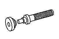


715 589 02 07 00
Socket
714 589 05 15 00
Mandrel
715 589 03 15 00
Centering mandrel
715 589 01 31 00
Immobilizer device


000 589 30 33 00
Inner puller
000 589 34 33 00
Counter support
715 589 18 63 00
Fastening device
715 589 15 63 00
Tensioning plates


000 589 45 33 00
External puller
001 589 80 21 00
Torque wrench
Produtos para reparos
Número | Denominação | Número de pedido |
BR00.45-B-1010-02A | Fast-drying adhesive | A 002 989 93 71 |
Produtos para reparos
Número | Denominação | Número de pedido |
BR00.45-B-1015-02B | Loctite 242 | Henkel Loctite |
BR00.45-B-1029-02B | Surfaces sealing product Loctite 5203 | Henkel Loctite |
BR00.45-B-1033-02B | Loctite 243 | Henkel Loctite |
Produtos para reparos
Número | Denominação | Número de pedido |
BR00.45-B-1021-06A | Synthetic grease | A 001 989 32 51 |
BR00.45-B-1056-06A | Vaseline - DBL 6850.00 | A 000 989 15 51 |
Referenced documents
- ap2600b2601k Manual transmission - oil change
- ar2610b0020bj Remove/install transmission
- ar2618b0001ba Detach/attach compressed air line
- ar2618b2000bd Remove/install gear shift cylinder
- ar2620b1005bka Remove/install gate module
- ar2620b1020ba Remove/install gear sensor
- ar2630b0310bb Remove/install rear transmission cover
- ar2630b1020bkb Remove/install input shaft bearing cap
- ar2635b100001ba Determine shim for shift piston of splitter group
- ar2635b100002ba Determine shim for cylindrical actuator of cascade box
- ar2635b100003ba Remove/install radial shaft seal and pilot bushing for splitter group shift rod
- ar2635b1000ba Remove/install shift rod and shift piston for splitter group
- ar2640b2475bg Remove/install rear section of transmission housing
- ar2650b0001be Remove/install main shaft and countershaft
- ar2650b041003bkb Determine shims of drive shaft and countershaft
- ar2650b042012ba Checking wear limit between synchronizer cone and sliding sleeve
- ar2650b0420br Disassemble and assemble main shaft
- ar2650b2000bb Remove/install transmission output flange
- ar2650b200201b Remove/install reverse idler shaft with reverse gear
- ar2650b4744bh Dismantle, assemble drive shaft.
- ar2650b4775bo Disassemble, assemble countershaft
- ar2650b6000bka Remove/install countershaft brake (VGW-B)
- ar2660b0001bp Remove and install gearshift system
- ar2660b0010bd Remove/install shift forks and shift rails
- ar4210b0900a Remove/install compressed air connector coupling
- ar4210b0900b Remove/install compressed air connector coupling
- ar4330b0002a Remove/install retarder
- wf5850b263501a Assembly tool for installing splitter group shift rod
- wf5850b310001a Guide bolt for installing range group