AR26.10-B-0010TC | Assemble transmission | 12.02.16 |
Manual transmission 715.504, 715.517, 715.527 with Vehicle 693, 696, 958 with CODE GS1 (Manual gearshift)
Manual transmission 715.527 with Vehicle 958 with CODE GS2 (Telligent gearshift)

W26.50-1061-09
1 Countershaft's cover
2 Countershaft bearing cap (front)
3 Input shaft cover
4 Input shaft bearing cap (front)
5 O-ring
6 Lock
7 Front housing
8 Sliding skids
9 Split group's shift fork
10 Oil tube
11 Countershaft
12 Countershaft bearing cap (rear)
13 Reverse gear gearwheel
14 Range group
15 Pin of the shift fork of the 1st/2nd, 3rd/4th and reverse gear
16 Center housing
17 Main shaft bearing cap (rear)
17.1 Shim (only modified center housing (16))
18 Main shaft (with control unit)
19 Synchronizer cone with synchronizer ring and annular spring
20 Input shaft
21 Control unit
22 Bolt of the split group fork
23 Reverse gear gearwheel shaft
B3 Countershaft's revs sensor
B47 Oil temperature sensor
S9 Neutral sensor

W26.40-1024-02
16 Center housing
A Distance (sealing surface to the bearing lodging)
| Assembling | ||
1 | Assemble the countershaft (11) | ||
2 | Assemble the input shaft (20) | ||
3 | Install the main shaft (18) | ||
4 | Measure the distance (A) from the sealing surface to the bearing lodging in the center housing (16) | If the distance (A) is 327.5 mm, the shim (17.1) is not installed. | |
If the distance (A) is 328.5 mm, the shim (17.1) has to be installed under the taper roller bearing cap (17). | |||
5 | Place the shim (17.1) on the taper roller bearing cap (17) | Only if the distance (A) in the center housing (16) is 328.5 mm. | |
6 | Assemble the taper roller bearing cap (12,17) and if necessary with the shim (17.1) in the center housing (16) | Apply multipurpose grease on the taper roller bearing caps (12, 17). | |
Utilize an appropriate mandrel. | |||
7 | Mount the reverse gear gearwheel (13) with bearing and bushing | The long collar of the reverse gear gearwheel (13) must point to the output side. | |
8 | Install the immobilizer device in the oil hole on the main shaft (18) | Immobilizer device | |
9 | Assemble the shift fork of the 3rd/4th gear, then the one of the 1st/2nd gear with the sliding skates with the control bars on the main shaft, engage the reverse gear control bar in the immobilizer device | Observe the assembly sequence. | |
10 | Place the countershaft (11) in the immobilizer device | ||
11 | With the immobilizer device, install the assembly of main shaft (18), and countershaft (11) in the center housing (16) | ||
12 | Assemble the pins of the shift forks of the 1st/2nd, 3rd/4th and reverse gear (15) | Assemble the pins of the shift forks of the 1st/2nd, 3rd/4th and reverse gear (15) with fast drying adhesive. | |
| |||
13 | Remove the immobilizer device | ||
14 | Assemble the synchronizer cone with the synchronizer ring and annular spring (19) | The long collar must point to the output side. | |
15 | Assemble the input shaft (20) | Move the countershaft (11) aside and apply multipurpose grease on the taper roller bearing (pilot bearing). | |
16 | Center the reverse gear gearwheel (13) and assemble the reverser gear shaft (23) | | |
17 | Assemble the oil tube (10) | ||
18 | Assemble the shift fork of the split group (9) with the sliding skates (8) | ||
19 | Place the centering mandrel on the oil tube (10) | Centering mandrel | |
20 | Place the guide pins in the front housing (7) | ||
| Guide pin for installing the split group | ||
21 | Fit the front housing (7) on the center housing (16) | Apply sealing compound on the sealing surfaces. | |
The control bars must slide on the guide of the front housing (7). | |||
22 | Assemble the lock (6) on the oil tube (10) and remove the centering mandrel from the oil tube (10) | ||
23 | Remove the guide pin from the front housing (7) and place the fastening bolts of the front housing (7) | Observe the different bolt lengths. | |
| |||
24 | Assemble the taper roller bearing caps (2, 4) | Apply multipurpose grease on the taper roller bearing caps (2, 4). | |
Utilize an appropriate mandrel. | |||
25 | Install the radial seal and the guide bushing of the control rod of the split group | ||
Mandrel | |||
Synthetic grease | |||
26 | Install the split group's control rod | The shift fork of the split group (9) has to engage in the recess of the control rod. | |
27 | Assemble shift fork pin of the split group (22) | Apply fast drying adhesive on the shift fork pin of the split group (22). | |
| |||
28 | Assemble the countershaft cover (1) and the input shaft cover (3) | ||
29 | Place the gearbox in the horizontal | ||
30 | Determining the compensating washer for the split group's shift piston | ||
31 | Lift out the control rod with the assembly tool | ||
| Assembly tool to install the control rod of the split group | ||
32 | Assemble the double groove seal and the shift piston | Apply synthetic grease on the double groove seal. | |
Lock the shift piston with fast drying adhesive. | |||
| |||
Fitting wrench | |||
33 | Determining the compensating washer for the split group's command cylinder | ||
Inside puller | |||
Counter-support | |||
34 | Assemble the control unit (21) | Vehicles with code (GS1) "manual" gearbox actuation. | |
Vehicles with code (GS2), electro-pneumatic gear shifting. | |||
35 | Assemble the range group (14) | ||
36 | Install the range group (14) | ||
37 | Install the neutral sensor (S9) | Only vehicles with code (GS1) "manual" gearbox actuation. | |
| |||
38 | Install the oil temperature sensor (B47) | | |
39 | Install the countershaft revs sensor (B3) | | |
40 | Connect the electric wires on the connectors and supports | ||
41 | Install the clutch throw-out lever | |
Splitter group
Número | Denominação | Gearboxes 715.504, 715.517, 715.527, 715.564 | |||
BE26.35-B-1001-01A | Adjusting measurement of the split group shift piston | mm | 0,3...0,5 | ||
BE26.35-B-1002-01A | Adjusting measurement of the split group shift cylinder | mm | 0,4...0,5 | ||
Clutch operator
Número | Denominação | Chassis 958.0, 958.1 | Chassis 934.2, 958.2, 958.4 | |||
BA25.20-B-1001-01L | Fork in the gearbox | M12 | Nm | 90 | 90 | |
M10 | Nm | 60 | 60 | |||
Sensors
Número | Denominação | Gearboxes 715..., with mechanical speed command | Gearboxes 715..., with EPS speed command | |||
BA26.19-B-1006-01B | Oil temperature transmitter in the gearbox | Nm | 60 | 60 | ||
BA26.19-B-1007-01B | Over-speed switch in the gearbox | Nm | 40 | 40 | ||
BA26.19-B-1010-01B | Neutral position switch | Nm | 60 | - | ||
Splitter group
Número | Denominação | Gearboxes 715.504/517/527 | |||
BA26.35-B-1001-01B | Selector fork retaining pin in the gearbox | Nm | 120 | ||
BA26.35-B-1002-01B | Fastening of the split group's shift piston | With special tool | Nm | 90 | |
without special tool | Nm | 95 | |||
Housing
Número | Denominação | Gearboxes 715.50/51/52, 715.56, 715.540 | |||
BA26.40-B-1004-01D | Housing on the center part of the gearbox | Nm | 80 | ||
BA26.40-B-1006-01D | Support pins (threaded) of the gearbox selection forks | Nm | 120 | ||
BA26.40-B-1007-01D | Reverse gear retainer plate on the gearbox | Nm | 60 | ||

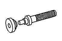


715 589 02 07 00
Fitting wrench
714 589 05 15 00
Mandrel
715 589 03 15 00
Centering mandrel
715 589 01 31 00
Retaining device


000 589 30 33 00
Inside puller
000 589 34 33 00
Counter-support (block)
Produtos para reparos
Número | Denominação | Número de pedido |
BR00.45-B-1006-02A | Adhesive mass Loctite 242 | A 003 989 31 71 |
BR00.45-B-1010-02A | Fast-drying adhesive | A 002 989 93 71 |
Produtos para reparos
Número | Denominação | Número de pedido |
BR00.45-B-1029-02B | Surfaces sealing product Loctite 5203 | Henkel Loctite |
Produtos para reparos
Número | Denominação | Número de pedido |
BR00.45-B-1021-06A | Synthetic grease | A 001 989 32 51 |
BR00.45-B-1056-06A | Vaseline - DBL 6850.00 | A 000 989 15 51 |
Referenzierte Dokumente
- ar2630b1010ta
- ar2631b3102ta Bereichsgruppe einbauen
- ar2631b3201ta Bereichsgruppe zusammenbauen
- ar2635b100001a Ausgleichscheibe für Schaltkolben der Vorschaltgruppe ermitteln
- ar2635b100002ta Ausgleichscheibe für Schaltzylinder der Vorschaltgruppe ermitteln
- ar2635b100003ta Radialwellendichtring und Führungsbuchse für Schaltstange der Vorschaltgruppe aus-, einbauen
- ar2635b1000ta Schaltstange und Schaltkolben der Vorschaltgruppe aus-, einbauen
- ar2650b0426ta
- ar2650b4744ta
- ar2650b4775tb
- ar2660b0001tb
- ar2660b0001te
- wf5850b263501a
- wf5850b310001a