SI33.30-P-0006A | Service Information: changed repair method of front axle supporting ball joint for removal of front axle shaft | 19.1.11 |
MODEL 169, 245 (except , 245.286)


P33.20-2204-01
P33.20-2205-01
P33.20-2203-01
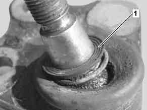
Picture 1
Bellows damage after too deep taper pull-in
Figure 3
The installation position should be marked before dismantling the 3 bolts
Picture 2
Bellows damage due to the steering knuckle
Two repair methods have been adapted as part of continuous further development of repair methods, in particular taking into account knowledge from damaged part findings.
The documents listed below have been maintained with WIS update 04/2007
1. Separation of front axle shaft and front axle shaft flange
On account of the risk of damage to the wheel bearings a seized front axle shaft must not be hammered out using a drift and hammer. The extraction and insertion tool 210 589 03 43 00 must be used for pressing out.
Proceed as follows to avoid damage to the splined shaft:
After loosening the collar nut, spray the front axle shaft stub at the front axle shaft flange with antiseize and allow to take effect.
Once the repair is completed mount the hub cap on the front axle.
2. Separation of transverse control arm and steering knuckle
If during assembly of a conical joint the most meticulous attention is not paid to ensure that no grease or oil enters the conical joint, the cone will be drawn in too far when tightening to the specified torque.
The bellows then contacts the steering knuckle and can no longer turn freely. This leads to bellows cracks and bellows damage (picture 1).
Furthermore it has been found that many bellows exhibit cut damage which is caused by the steering knuckle when guiding out the ball stud.
If, after guiding out the ball stud, the flange joint is allowed to slide along the steering knuckle, the bellows will be cut into by the sharp lower edge of the steering knuckle. (Figure 2).
In order to avoid this in future, during the corresponding repair work with immediate effect the transverse control arm is to be separated from the steering knuckle by removing the flange ball joint (3 bolts) from the transverse control arm and no longer via the separation of the conical joint. If the flange ball joint is aligned to the transverse control arm in the old installation position (picture 3) again, a chassis alignment check is no longer required.
Remove/install transmission | Transmission 711.640 in model 169.0/3, 245.2 Transmission 716.522 in model 169.0/3 | ||
Remove/install transmission | Transmission 716.5 in model 169.0/3, 245.2 | ||
Remove/install transmission | Transmission 711.6 in model 169.0/3, 245.2 | ||
Remove/install front axle carrier | Model 169.0/3 Model 245.2 | ||
Remove/install front axle shaft flange and double-row angular ball bearing | Model 169.0/3, 245.2 | ||
Remove/install flange ball joint | Model 169.0/3, 245.2 | ||
Remove/install front axle shafts | Left front axle shaft | ||
Model 169.0/3, 245.2 except 169.090 | |||
Model 169.090 | |||
Extraction and insertion tool | |||
Remove/install front axle shafts | Right front axle shaft | ||
Model 169.0/3, 245.2 except 169.090 | |||
Model 169.090 | |||
Extraction and insertion tool | |||
Remove/install steering knuckle | Model 169.0/3, 245.2 | ||
Press front axle shafts out of the front axle shaft flange | Model 168, 169, 245 | ||
Checking accident vehicles and vehicles possibly damaged in an accident | Model 169.0/3, 245.2 | ||
Replace longitudinal member front section | Model 169.0/3 | ||
Replace longitudinal member front section | Model 245.2 |

Extraction and insertion tool
210 589 03 43 00
Parts ordering notes
Part no. | Designation | Quantity |
A 168 357 00 89 | Hub cover | As required |
Odkazované dokumenty
- ar2610p0020ak
- ar2610p0020al
- ar2610p0020bk
- ar3310p0001ak
- ar3320p0315ak
- ar3320p0446ak
- ar3325p0400ak
- ar3330p062004gc Vytlačit hnací hřídel přední nápravy z příruby hnacího hřídele přední nápravy
- ar3330p0620ak
- ar3330p0620akl
- ar3330p0620akr
- ar3330p0620al
- ar4030p0400ak
- ar6220p1260ak
- ar6220p1260bk