AR01.10-W-2401A | Remove/install engine with transmission | 14.2.12 |
ENGINES 904.9 in MODELS 673, 674, 676

W01.10-0001-09
1 Engine
2 Compressed-air line
3 Electrical connector
4 Electrical connector
5 Propeller shaft
6 Clutch slave cylinder
7 Electrical connector
8 Electrical connector
9 Fuel feed line
10 Fuel return pipe
11 Compressed-air line
12 Gearshift linkage
13 Screw
14 Engine mount
15 Frame crossmember
16 Oil dipstick guide tube
17 Electrical engine wiring harness
(for code (M89) Flame starting system (FLA))
18 Electrical engine wiring harness
(for code (M89) Flame starting system (FLA))
A6 MR/PLD control unit
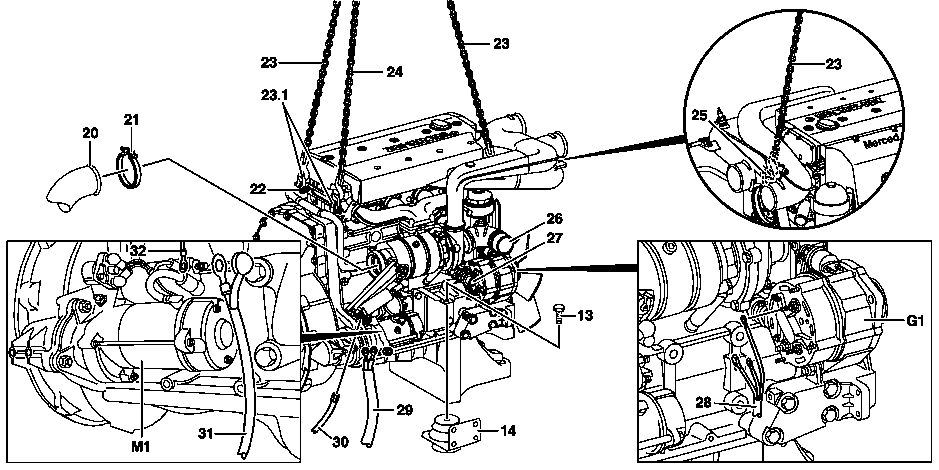
W01.10-0016-09
13 Screw
14 Engine mount
20 Exhaust pipe
21 Clip
22 Lifting eye
23 Engine hoist
23.1 Shackle
24 Chain tackle
25 Lifting eye
26 Air intake hose
27 Air intake hose
28 Wiring harness
29 Ground cable
30 Compressed-air line
31 Circuit 30 cable
32 Circuit 50 cable
M1 Starter
G1 Generator


W01.10-0004-01
W01.10-0003-01
5 Propeller shaft
7 Electrical connector
33 Screw
34 Nut
35 Transmission mounting
Modification notes
30.3.05 | Tightening torque for terminal 30 at starter - added | Step 11 | |
Tightening torque for electrical wiring harness at alternator - added | Step 12 |
| Remove/install | ||
Danger! | Risk of explosion caused by escaping oxyhydrogen gas. Risk of injury caused by caustic burns to eyes, skin and mucous membranes from battery electrolyte (contains diluted sulfuric acid) or metal spatter due to short circuit. Risk of burn injuries caused by short circuit. Risk of poisoning caused by swallowing battery electrolyte (contains diluted sulfuric acid) or absorption of lead over the skin or orifices | No fire, sparks, open flames or smoking. Wear acid-resistant gloves and clothing and safety glasses with side guards. Do not place any conductive objects on the battery and avoid any short circuit from battery positive to ground. Only fill liquid battery electrolyte (diluted sulfuric acid) into suitable and appropriately marked containers. | |
1 | Disconnect ground lead from battery | ||
| Notes on battery | ||
2 | Tilt cab into repair position | ||
3 | Remove rear cab mount | ||
4 | Remove soundproofing on the left and right at frame and below | ||
5 | Remove radiator with charge air cooler | ||
6 | Bind oil dipstick guide tube (16) to engine (1) | ||
7 | Detach exhaust pipe (20) from engine brake valve connection | Installation: Clean sealing surfaces. Check the clamp (21) for wear, replace if necessary. | |
8 | Detach compressed air line (30) from engine brake cylinder | ||
9 | Remove air intake hose (26) for turbocharger and air intake hose (27) for compressor | ||
10 | Disconnect electrical engine wiring harness (17, 18) at flame glow plug and solenoid valve | Only for code (M89) Flame starting system (FLA). | |
11 | Disconnect lines for circuit 30 (31) and circuit 50 (32) from starter (M1) | | |
12 | Disconnect wiring harness (28) from generator (G1) | Mark lines. | |
Installation: Note markings. | |||
| |||
| |||
| |||
13 | Remove ground line at timing case (29) | ||
14 | Detach shift linkage (12) from transmission shift mechanism | ||
15 | Remove clutch slave cylinder (6) at transmission and bind to frame with hydraulic line connected | Installation: Grease the thrust pins. | |
16 | Unbolt compressed air line (2) at compressor and inspect for carbon deposits | If carbon deposits are present, it is also necessary to inspect compressed air line (2) between compressor and compressed air drier and four-circuit protection valve. Replace parts showing carbon deposits. | |
Installation: Check compressed-air line (2) for leaks. | |||
Danger! | Risk of explosion caused by ignition of flammable products, risk of poisoning caused by inhaling fuel vapors or swallowing fuel as well as risk of injury to skin and eyes exposed to fuel. | No fire, sparks, open flames or smoking. Wear protective clothing when handling fuel. | |
17 | Disconnect fuel feed line (9) at fuel pump and fuel return line (10) at fuel filter and bind to the side | Mark fuel feed line (9) und fuel return line (10). Collect escaping fuel. | |
| |||
18 | Disconnect pressure line (11) for constant throttle | ||
19 | Release and disconnect connector (8) on MR/PLD control unit (A6) | ||
20.1 | Remove power steering pump and bind to one side with attached steering pressure line and steering suction line | Not if a reconditioned engine is installed. | |
| |||
Danger! | Risk of injury to skin or eyes caused by hydraulic fluid spraying out under high pressure. Risk of poisoning caused by swallowing hydraulic fluid | Depressurize hydraulic system completely before starting any work on system. Wear protective clothing and safety glasses. | |
20.2 | Disconnect both hoses at steering pressure line and steering suction line | Only if a reconditioned engine is installed. | |
21 | Remove frame cross member (15) | Under radiator and engine (1). | |
22 | Attach engine hoist (23) at the front to lifting eye (25) of coolant pump and guide upwards | Load regulator gotis://H_00.12_04.0 | |
23 | Attach engine hoist (23) at rear left to lifting eye (22) | Insert shackles (23.1) as an intermediate pieces so that engine hoist (23) does not damage cylinder head cover. | |
Shackle, DIN 82101 | |||
Load regulator gotis://H_00.12_04.0 | |||
24 | Attach chain tackle (24) at right rear to lifting eye (22) and tension chains on the engine hoist (23) and chain tackle (24) | Insert shackles (23.1) as an intermediate pieces so that chain hoist (24) does not damage charge air manifold. Secure engine to prevent it from tilting. | |
Shackle, DIN 82101 | |||
Load regulator gotis://H_00.12_04.0 | |||
25 | Disconnect electrical connector (3, 4, 7) at transmission | Installation: Replace lead seal (arrow) at electrical connector (7). | |
26 | Remove propeller shaft (5) at transmission and at frame | | |
27 | Unscrew bolt (33) from rear transmission mount (35) | Support transmission. | |
28 | Remove bolts (13) at left and right engine mounts (14) | Check engine mounts (14) for wear; replace engine mounts (14) if necessary. | |
29 | Remove engine (1) with removal fixture | Max. 30° tilt of engine (1) together with transmission when lifting out or inserting. | |
Load regulator gotis://H_00.12_04.0 | |||
30 | Remove transmission from engine (1) | For transmission 710 | |
With transmission 715 | |||
31 | Install in the reverse order | ||
32 | Check engine oil level using oil dipstick | ||
Danger! | Risk of accident caused by vehicle starting off by itself when engine is running. Risk of injury caused by contusions and burns during starting procedure or when working near the engine as it is running | Secure vehicle to prevent it from moving by itself. | |
33 | Start engine and observe oil pressure gauge with the engine idling | Crank engine with the starter for not more than 90 seconds. Repeat starting procedure after a break of approx. 2 minutes at the earliest. | |
34 | Bleed steering system | Only if a reconditioned engine is installed. | |
35 | Switch off engine and check for leaks | Visual inspection. | |
36 | Set time on tachograph | ||
37 | Enter engine number in FDOK | Only if a reconditioned engine is installed. |
Check values for engine oil pressure
Number | Designation | Engines | ||
BE18.00-N-1001-01C | Engine oil pressure at | Idling speed | bar | 0.5 |
maximum speed | bar | 2.5 | ||
Starter
Number | Designation | Engines | |
BA15.30-N-1002-01B | Nut, terminal 30 at starter | Nm | 30 |
Alternator
Number | Designation | Engines | ||
BA15.40-N-1010-01B | Nut, electrical line to alternator terminal B+ | Nm | 8 | |
BA15.40-N-1011-01B | Nut, electrical line to alternator terminal W | Nm | 4 | |
BA15.40-N-1012-01B | Nut, electrical line to alternator terminal B | Nm | 7 | |
Complete manual transmission
Complete manual transmission
Propeller shaft
Number | Designation | Model 673, 674, 675, 676, 677, 679 | ||
BA41.10-N-1002-01F | Bolt/nut, propeller shaft to flange connection | M10 | Nm | 60 |
M12 | Nm | 100 | ||
M14 | Nm | 160 | ||
M16 | Nm | 200 | ||
Power steering pump
Number | Designation | Steering | |
BA46.30-N-1001-01B | Bolt, power steering pump to compressor | Nm | 40 |
Fuel pipes/hoses
Number | Designation | Engine | ||
BA47.25-N-1008-01J | Nut, feed and return line to fuel filter | Nm | 45 | |
Repair materials
Number | Designation | Order number |
BR00.45-Z-1062-06A | Lubricating grease, Olista Longtime, DB supply specification 6804.60 | A 001 989 36 51 10 |