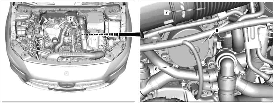
P20.00-2685-08
Shown on model 177 |
7 | Engine air intake duct downstream of the air filter | 9 | Vacuum pump | |
8 | Screw plug |
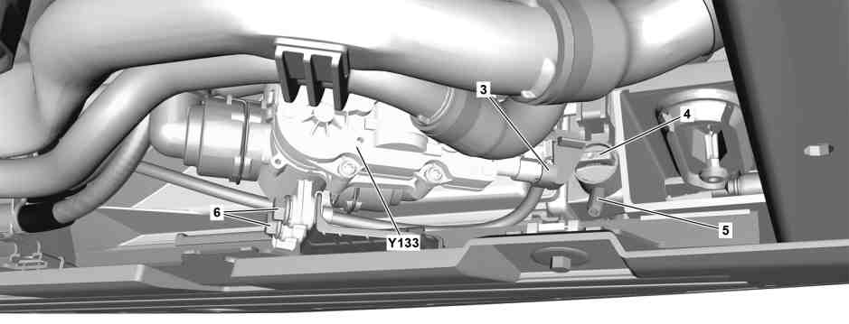
P20.00-2651-08
Shown on model 177 |
3 | Electrical connector | 6 | Bolts | |
4 | Drain screw | Y133 | Coolant pump switchover valve | |
5 | Drain fitting |
Danger | Risk of death caused by vehicle slipping or toppling off of the lifting platform. | Align vehicle between vehicle lift columns and position the four support plates at the vehicle lift support points specified by the vehicle manufacturer. | |
Warning | Risk of injury to skin and eyes suffering scalding from contact with hot coolantspray. Risk of poisoning from swallowing coolant. | Do not open cooling system unless coolant temperature is below 90 °C. Open cap slowly and release the pressure. Do not pour coolant into beverage containers. | |
Topical note | Information on preventing damage to electronic components due to electrostatic discharge | ||
Topical note | Notes on avoiding damage through contamination and foreign objects | ||
Topical note | Notes on coolant | ||
| Remove | ||
1 | Switch off ignition and store transmitter key outside of transmitter range (min. 2 m). | ||
2 | Remove lower engine compartment paneling | ||
3 | Release and disconnect electrical connector (3) from coolant pump switchover valve (Y133). | ||
4 | Remove screws (6) and place coolant pump switchover valve (Y133) to one side with connected lines. | | |
Drain off | |||
5 | Loosen cap from coolant expansion reservoir slowly, relieve overpressure, and then unscrew. | ||
6 | Attach suitable hose to the drain fitting (5) on the bottom right of the engine cooling system cooler. | ||
7 | Open drain screw (4) on engine cooling system cooler and drain off the coolant in a suitable container. | Observe regulations for disposal of coolant. | |
8 | Close drain screw (4) on engine cooling system cooler and detach drain hose. | ||
Pour in | |||
9 | Remove engine air intake duct downstream of the air filter (7). | ||
10 | Pour in coolant and bleed engine cooling system. | ||
Work procedure must be complied with when filling cooling system. | |||
Re-use clean coolant. | |||
Cooling system | |||
Test cap | |||
NTKL Adaption | |||
Electric vacuum pump | |||
Cooler vacuum filling device | |||
11 | Remove front screw plug (8) under the vacuum pump (9) on the thermostat and allow the coolant to drain somewhat. | Catch escaping coolant with a suitable container. | |
Cooler vacuum filling device | |||
12 | Tighten screw plug (8) on thermostat and correct coolant level. | ||
Notes on coolant level | |||
13 | Install engine air intake duct downstream of air filter (7). | ||
| Install | ||
14 | Position coolant pump switchover valve (Y133) on bracket and tighten screws (6). | | |
15 | Connect electrical connector (3) to coolant pump switchover valve (Y133). | | |
| Check | ||
16 | Check engine cooling system for leak tightness. | ||
Warning | Risk of accident from vehicle starting off by itself when engine running. Risk of injury (bruises and burns) resulting from working on the engine while it is being started or when it is running. | Secure vehicle to prevent it from starting off by itself. Wear closed and snug-fitting work clothes. Do not touch hot or rotating parts. | |
17 | Perform engine test run and check engine cooling system for proper operation and leak tightness. | ||
18 | Install lower engine compartment paneling. |
Cooling system |
Number | Designation | Engine 608 in model 118 | Engine 608 in model 177 | |||
BF20.00-P-1001-06F | Cooling system | Workshop replacement amount | Main circuit | Liter | 12,2 | 12,1 |
Antifreeze/water | to -37 °C | % | 50/50 | 50/50 | ||
as from -38 °C | % | 55/45 | 55/45 | |||
Specifications for Operating Fluids, sheet | ||||||
Specifications for Operating Fluids, sheet | ||||||
Specifications for Operating Fluids, sheet | ||||||
Cooling system |
Number | Designation | Engine 608 in model 247 | |||
BF20.00-P-1001-06F | Cooling system | Workshop replacement amount | Main circuit | Liter | 12,1 |
Antifreeze/water | to -37 °C | % | 50/50 | ||
as from -38 °C | % | 55/45 | |||
Specifications for Operating Fluids, sheet | |||||
Specifications for Operating Fluids, sheet | |||||
Specifications for Operating Fluids, sheet | |||||


285 589 01 21 00
NTKL Adaption
210 589 00 91 00
Test cap
285 589 02 21 00
Electric vacuum pump
285 589 00 21 00
Cooler vacuum filling device
Powiązane dokumenty
- ah0000p500001a Wskazówki dotyczące zapobiegania uszkodzeniom na skutek zabrudzeń i ciał obcych
- ah2000n208001a Wskazówki dotyczące płynu chłodzącego
- ah2000p114201cw Wskazówki dotyczące poziomu płynu chłodzącego
- ah5400p000101a Wskazówki dotyczące zapobiegania uszkodzeniom elementów elektronicznych na skutek rozładowania potencjału elektrostatycznego
- ar0910p8130mfe
- ar2000p1010mfe
- ar2000p114204a Napełnij płynem chłodzącym i odpowietrz układ chłodzenia.
- ar6120p1105mfe Demontaż i montaż dolnej wykładziny komory silnika
- as0000z000501a Niebezpieczeństwo wypadku na skutek samoczynnego ruszenia przy pracującym silniku. Niebezpieczeństwo obrażeń na skutek zmiażdżenia lub poparzenia przy wykonywaniu czynności podczas rozruchu lub przy pracującym silniku.
- as0000z001001a Zagrożenie życia na skutek ześlizgnięcia lub spadnięcia pojazdu z podnośnika.
- as2000z000101a Niebezpieczeństwo zranienia skóry i oczu przez poparzenie wytryskującym, gorącympłynem chłodzącym. Niebezpieczeństwo zatrucia na skutek połknięcia płynu chłodzącego