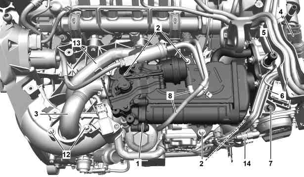
1 | High pressure exhaust gas recirculation cooler |
2 | Bolts |
3 | Exhaust gas recirculation line |
4 | Electrical connector |
5 | Ball stud |
6 | Engine wiring harnesses |
7 | Screw |
8 | Vacuum lines |
12 | Bolts |
13 | Coolant hose |
14 | Electrical connector |
P14.20-A010-05
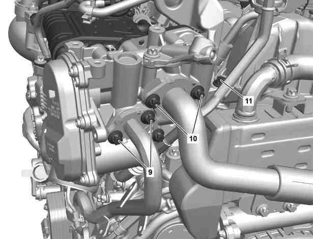
9 | Bolts |
10 | Bolts |
11 | Screw |
P14.20-A016-06
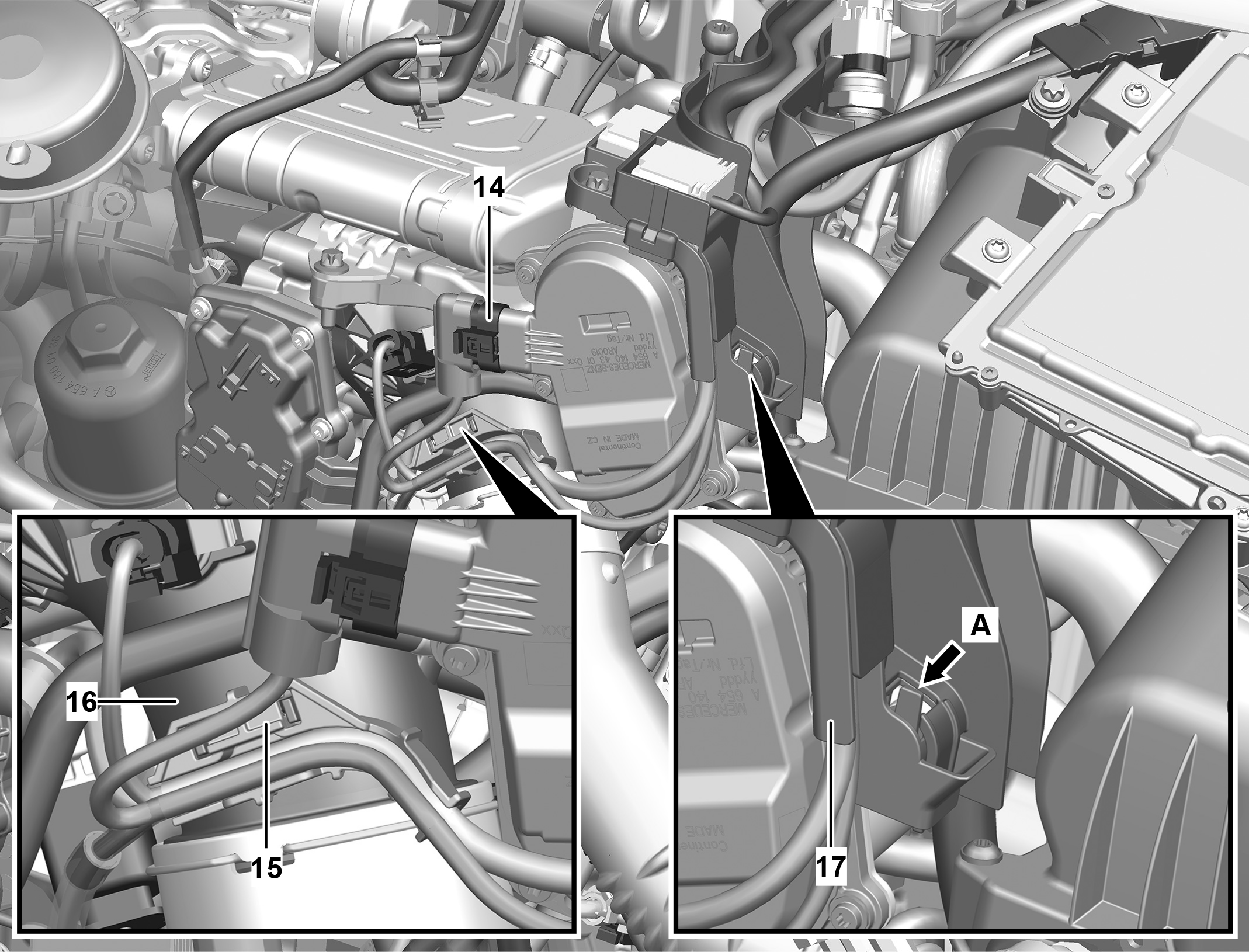
14 | Electrical connector |
15 | Bracket |
16 | Coupling flange |
17 | Cable duct |
P14.20-A020-06
Warning | Risk of burn injuries, suffocation and poisoning when working on the exhaust system and the components connected to it. Risk of suffocation and risk of poisoning caused by inhalation of gaseous and solid components of the exhaust. Risk of poisoning caused by skin contact with solid components of the exhaust. | Wear protective clothing and safety glasses. Use the extraction system. Move people out of the hazard area. | |
Warning | Risk of injury to skin and eyes suffering scalding from contact with hot coolantspray. Risk of poisoning from swallowing coolant. | Do not open cooling system unless coolant temperature is below 90 °C. Open cap slowly and release the pressure. Do not pour coolant into beverage containers. | |
Caution | Risk of injury caused by scraping or cutting body parts on sharp vehicle parts | Always wear protective gloves when working on or near sharp and non-deburred vehicle parts. | |
Topical note | Notes on threaded connections fastened using a tightening angle-based tightening process | ||
Topical note | Notes on avoiding damage through contamination and foreign objects | ||
| Remove | ||
1 | Drain off coolant. | ||
2 | Remove air filter housing. | ||
3 | Remove engine charge air duct from exhaust gas turbocharger. | ||
4 | Remove ball stud (5). | ||
5 | Remove screw (7). | ||
6 | Release and disconnect electrical connector (4). | ||
7 | Remove vacuum lines (8). | ||
8 | Remove exhaust gas recirculation cooler bypass switchover valve from high-pressure exhaust gas recirculation cooler (1) and place to one side with lines connected. | ||
| |||
9 | Remove bolts (12) and bolts at high-pressure exhaust gas recirculation cooler (1). | ||
10 | Remove exhaust gas recirculation line (3). | ||
11 | Remove O-ring and seal from exhaust gas recirculation line (3). | Assembly tool | |
12 | Remove coolant hose (13) from high-pressure exhaust gas recirculation cooler (1). | Hose clamp pliers | |
13 | Remove bracket (15) from coupling flange (16). | ||
14 | Release cable duct (17) (arrow A) and place to one side. | ||
15 | Release and disconnect electrical connector (14). | ||
16 | Place engine wiring harnesses (6) to one side. | ||
17 | Remove screws (2). | ||
18 | Remove screw (11) . | ||
19 | Remove screws (9). | ||
20 | Remove screws (10). | ||
21 | Remove high-pressure exhaust gas recirculation cooler (1). | The high-pressure exhaust gas recirculation cooler(1) is removed together with the high-pressure exhaust gas recirculation valve. | |
22 | Remove seal from coolant line at exhaust gas recirculation valve. | ||
23 | Remove seal from high-pressure exhaust gas recirculation line at high-pressure exhaust gas recirculation valve. | ||
| Clean | ||
24 | Clean all separation points. | Assembly cleaner | |
25 | Seal all openings with suitable protective covers, grommets, stop plugs. | Record plug | |
Set of plugs | |||
Set of protective caps | |||
Set of protective caps | |||
| Install | ||
26 | Remove protective covers, plugs, stop plugs. | Record plug | |
Set of plugs | |||
Set of protective caps | |||
Set of protective caps | |||
27 | Attach seal to coolant line at exhaust gas recirculation valve. | Replace seal. | |
28 | Attach seal to high-pressure exhaust gas recirculation line. | Replace seal. | |
29 | Install high-pressure exhaust gas recirculation cooler(1). | The high-pressure exhaust gas recirculation cooler(1) is installed together with the high-pressure exhaust gas recirculation valve. | |
30 | Attach O-ring and seal to exhaust gas recirculation line (3). | Replace O-ring and seal. | |
Assembly tool | |||
31 | Install exhaust gas recirculation line (3) and position on high-pressure exhaust gas recirculation cooler (1). | ||
32 | Screw in screw/bolts (2, 11, 12). | Tighten screws of high-pressure exhaust gas recirculation cooler | |
Replace screw/bolts (2, 11, 12). | |||
Bolt, exhaust gas recirculation valve to lifting eye | |||
Bolt, exhaust gas recirculation cooler to charge air distributor | |||
Bolt, exhaust gas recirculation line to charge air distributor | |||
33 | Slightly tighten screw/bolts (9, 10) by hand. | Pay attention to different lengths of screws. | |
Replace bolts (9, 10). | |||
34 | Tighten screws (9). | Bolt, coolant line to exhaust gas recirculation valve | |
35 | Tighten bolts (10). | Bolt, high pressure EGR line to high pressure exhaust gas recirculation valve | |
36 | Clip engine wiring harnesses (6) into working area. | ||
37 | Connect and lock electrical connector (14). | ||
38 | Attach cable duct (17) to high-pressure exhaust gas recirculation valve and lock (arrow A). | ||
39 | Attach bracket (15) to coupling flange (16). | ||
40 | Attach coolant hose (13) to high-pressure exhaust gas recirculation cooler (1). | Hose clamp pliers | |
41 | Install exhaust gas recirculation cooler bypass switchover valve on high-pressure exhaust gas recirculation cooler (1). | ||
42 | Install vacuum lines (8). | ||
43 | Connect and lock electrical connector (4). | ||
44 | Screw in screw/bolt (7). | M61 | |
45 | Screw in ball stud (5). | Ball stud on engine cover to high pressure exhaust gas recirculation valve | |
46 | Install engine charge air duct at exhaust gas turbocharger. | ||
47 | Install air filter housing. | ||
Only install upper engine cover after the leak test. | |||
48 | Fill in coolant. | ||
| Check | ||
Warning | Risk of accident from vehicle starting off by itself when engine running. Risk of injury (bruises and burns) resulting from working on the engine while it is being started or when it is running. | Secure vehicle to prevent it from starting off by itself. Wear closed and snug-fitting work clothes. Do not touch hot or rotating parts. | |
49 | Start engine and read out actual value of exhaust gas temperature upstream of diesel oxidation catalytic converter in CDI control unit (N3/9). | ||
| |||
50 | Check activation of exhaust gas recirculation. | Exhaust gas recirculation is active from an exhaust gas temperature of at least 155 °Cupstream of the diesel oxidation catalytic converter and in the idle to mid-partial load range. | |
51 | Check high-pressure exhaust gas recirculation cooler (1) for leaks. | ||
52 | Switch off engine. | ||
53 | Install upper engine cover. | ||
54 | Read out fault memory and delete if necessary. | ||
|


000 589 93 63 00
Assembly tool
454 589 00 37 00
Hose clamp pliers
199 589 00 98 00
Set of plugs
001 589 00 91 00
Set of protective caps


129 589 00 91 00
Record plug
001 589 02 91 00
Set of protective caps
Powiązane dokumenty
- ad0000p200006mfa
- ah0000p002001a Wskazówki dotyczące połączeń śrubowych tworzonych według kąta dokręcenia
- ah0000p500001a Wskazówki dotyczące zapobiegania uszkodzeniom na skutek zabrudzeń i ciał obcych
- ar0110p2405mff
- ar0910p1150mff
- ar0941p8622mff Demontaż i montaż kanału powietrza doładowywanego do turbosprężarki
- ar1420p000101mff
- ar1420p7667mff Demontaż i montaż zaworu przełączającego obwodu obejściowego chłodnicy recyrkulacji spalin
- ar2000p1142mff
- as0000z000501a Niebezpieczeństwo wypadku na skutek samoczynnego ruszenia przy pracującym silniku. Niebezpieczeństwo obrażeń na skutek zmiażdżenia lub poparzenia przy wykonywaniu czynności podczas rozruchu lub przy pracującym silniku.
- as0000z001701a Niebezpieczeństwo obrażeńo elementy pojazdu o ostrych krawędziach.
- as2000z000101a Niebezpieczeństwo zranienia skóry i oczu przez poparzenie wytryskującym, gorącympłynem chłodzącym. Niebezpieczeństwo zatrucia na skutek połknięcia płynu chłodzącego
- as4900z000101a Niebezpieczeństwo poparzenia, uduszenia i zatrucia podczas prac przy układzie wydechowym i połączonych z nim elementach. Niebezpieczeństwo uduszenia i zatrucia przez wdychanie gazowych i stałych składników spalin. Niebezpieczeństw