
P63.50-3467-09
1 Position metal needle template (2) offset on Y-markings (arrows) approx. 10 mm toward rear and scribe (area A).
When the C-pillar is damaged, transfer Y-marking (arrows) upward according to dimension (a), position metal needle template (2) and scribe cut (area A1).
Dimension (a) is 120 mm.
2 Cut along broken line using body saw (area A or A1).
Observe sheet metal below.
3 Expose spot welds on rear fender (1) and cut out (area B).
4 Expose MIG weld seam on rear fender (1) and grind open (area C).

P63.50-3423-11
5 Scribe cut on rear fender (1) using cutting template and according to dimensions (b, c) (area E).
Dimension (b) is approx. 82 mm and dimension (c) is approx. 329 mm.
6 Cut on rear fender (1) using body saw (area E).
Observe sheet metal below.
7 Expose spot welds on rear fender (1) and cut out (areas D and F).

P63.50-3424-06
8 Expose clinch connections on rear fender (1) and drill with 6.0 mm dia. bit (areas G and I).
9 Expose punch rivets on rear fender (1) and cut out (area H).
10 Expose spot welds on rear fender (1) and cut out (areas J1, J2 and J3).

P63.50-3465-09
11 Expose clinch connections and resistance spot welds on rear fender (1) and cut out (areas K, L, M and Q).
12 Expose punch rivet and clinch connections on rear fender (1) and drill with 6.0 mm dia. bit (areas N, O, P and R).
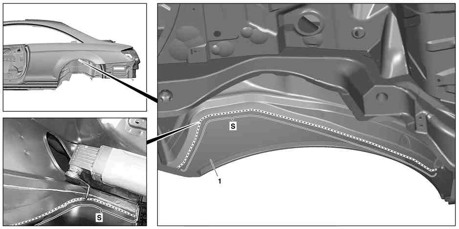
P63.50-3463-09
13 Cut bonded connection between outer rear wheelhouse and rear fender (1) using multicutter (area S).

P63.50-3427-09
14 Heat rear fender in cross-hatched areas with hot air gun and remove.
The rear fender is foam-protected and bonded in cross-hatched areas.Damaged foam parts must be removed and replaced.

P63.50-3431-09
For all other operation steps, observe information on pretreatment of bonding surfaces.
15 Remove adhesive residues in cross-hatched areas using round wire brush (areas T, U, V, V1, W, X1, X2, X3 and X4).
16 Grind mating surfaces down to bare metal in cross-hatched areas on both sides using round wire brush (areas U, X2, V1 and W1).
17 Grind mating surfaces down to bare metal in other cross-hatched areas on one side using round wire brush.
18 Cut off adhesive residues using scraper (area Y).
A maximum of 2 mm of adhesive residue may be left. Pull off loose adhesive material (remaining pieces which are not completely cut off).
19 Remove grinding and drill shavings using wet/dry vacuum cleaner.
20 Coat insides of spot weld flange with zinc dust paint (area V1).

P63.50-3432-06
21 Cut upper C-pillar to size using body saw and crimp toward inside using sheet metal crimping pliers (area AA).
Use shop-made sheet metal crimping pliers for areas difficult to be accessed.
22 Remove adhesive residues in cross-hatched areas using stainless steel round wire brush and grind mating surfaces down to bare metal on one side (area AB).
23 Remove adhesive residues in cross-hatched areas using round wire brush and grind mating surfaces down to bare metal on one side (area AF).
24 Grind mating surfaces down to bare metal in cross-hatched areas using round wire brush on one side (areas AC, AD and AE).
25 Remove grinding and drill shavings using wet/dry vacuum cleaner.
26 Coat insides of spot weld flange with zinc dust paint (areas AC, AD and AE).

P63.50-3468-11
27 Remove adhesive residues in cross-hatched areas using stainless steel round wire brush and grind mating surfaces down to bare metal (areas Z, Z1 and Z2).
28 Remove grinding and drill shavings using wet/dry vacuum cleaner.