
Shown on model 910.6, left side of vehicle |
1 | A-pillar paneling |
D63.20-1471-06

Shown on model 907 with engine 651 |
2 | Windshield wiper system for windshield |
3 | Ventilation box |
4 | Frame seal |
5 | Electrical wiring harness |
6 | Passage grommet |
7 | Vapor barriers |
8 | Electrical wiring harness |
9 | Passage grommet |
10 | Vapor barriers |
11 | Ground lines |
12 | Engine hood cable |
13 | Diesel injection system control unit |
14 | Hose |
D60.00-A008-06
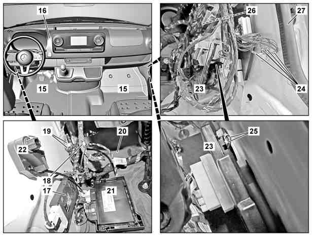
Shown on model 907 |
15 | Front floor covering |
16 | Instrument panel |
17 | Electronic ignition switch control unit |
18 | Electrical wiring harness |
19 | Ground lines |
20 | Damping material |
21 | Common Powertrain Controller (CPC) control unit |
22 | Hood release cable release |
23 | Signal acquisition and actuation module (SAM) control unit |
24 | Ground lines |
25 | Ground lines |
26 | Damping material |
27 | Frame seal |
D60.00-A009-06
Danger | Risk of death when working on component parts and systems with U >= 30 V alternating voltage (AC) or U >= 60 V direct voltage (DC) | Do not touch damaged or defective live component parts and lines or non-insulated electrical connections and lines.Model 910 with engine 780.703 | |
Danger | Risk of death caused by vehicle slipping or toppling off of the lifting platform. | Align vehicle between vehicle lift columns and position the four support plates at the vehicle lift support points specified by the vehicle manufacturer. | |
Topical note | General information on vehicles with high-voltage on-board electrical system and/or lithium-ion battery and/or gaseous-fuel drive system as well as personal protective equipment | Model 910 with engine 780.703 | |
Topical note | Notes on battery | Model 910 with engine 780.703 | |
Topical note | Information on preventing damage to electronic components due to electrostatic discharge | ||
Topical note | Notes on carrying out repair work in the vehicle interior | ||
| Remove/install | ||
1 | Remove respective hinge of the front door. | ||
2 | Remove respective door holder. | ||
3 | Remove respective boot from the A-pillar paneling (1). | Guide electric lines through the opening in the A-pillar paneling (1) and position in the vehicle interior outside of the working area. | |
The number of electrical connectors may vary depending on the equipment. | |||
4 | Remove hood. | ||
5 | Remove rear section of respective front fender liner. | ||
6 | Remove respective sealing frame (27) in the repair area and position outside of the working area. | ||
7 | Remove each front wheel. | ||
8 | Remove front section of respective front fender liner. | ||
9 | Remove respective front fender. | ||
10 | Remove respective front bottom fender. | ||
11 | Remove hose (14) and position outside of the working area. | If left side of vehicle is damaged. | |
12 | Remove windshield wiper system for windshield (2). | In the event of damage to the driver's side. | |
13 | Remove ventilation box (3). | In the event of damage on the front passenger side. | |
Model 907 with engine 274 | |||
14 | Remove sealing frame (4) in the repair area and position outside of the working area. | ||
15 | Remove electrical wiring harness (5) in the repair area and position outside of the working area. | If right side of vehicle is damaged. | |
16 | Remove feed-through grommet (6) in the repair area and position outside the working area. | If right side of vehicle is damaged. | |
17 | Remove damping (7) in the repair area and position outside of the working area. | If right side of vehicle is damaged. | |
18 | Remove electrical wiring harness (8) in the repair area and position outside of the working area. | If left side of vehicle is damaged. | |
19 | Remove feed-through grommet (9) in the repair area and position outside the working area. | If left side of vehicle is damaged. | |
20 | Remove damping (10) in the repair area and position outside of the working area. | If left side of vehicle is damaged. | |
21 | Remove ground lines (11) and position outside of the working area. | If left side of vehicle is damaged. | |
M6 | |||
22 | Remove hood cable (12) from the hood catch lower section and position outside of the working area. | If left side of vehicle is damaged. | |
| |||
23 | Remove diesel injection system control unit (13). | If left side of vehicle is damaged. | |
Model 907 with engine 642 | |||
24 | Remove Electronic Stability Program (ESP®) hydraulic unit. | In the event of damage to the driver's side. | |
25 | Remove windshield. |
| |
Model 907, 910 | |||
26 | Remove respective underfloor paneling. |
| |
27 | Remove front roof lining. | ||
28 | Remove respective window airbag. | ||
29 | Remove respective front door sill trim. | ||
30 | Remove front floor covering (15). |
| |
Model 910 | |||
31 | Remove instrument panel (16). | ||
32 | Remove electronic ignition lock control unit (17). | If left side of vehicle is damaged. | |
Model 907 | |||
33 | Remove electronic ignition lock control unit (17). | If right side of vehicle is damaged. | |
Model 910 | |||
34 | Remove electrical wiring harness (18) in the repair area and position outside of the working area. | If left side of vehicle is damaged. | |
35 | Remove ground lines (19) and position outside of the working area. | If left side of vehicle is damaged. | |
M6 | |||
36 | Remove damping (20) in the repair area and position outside of the working area. | If left side of vehicle is damaged. | |
37 | Remove CPC control unit (21). | If left side of vehicle is damaged. | |
38 | Remove exhaust aftertreatment system control unit. | If right side of vehicle is damaged. | |
Model 907 with engine 642 | |||
39 | Remove hood release cable release (22) and position outside of the working area. | If left side of vehicle is damaged. | |
40 | Remove SAM control unit (23). | If right side of vehicle is damaged. | |
Model 907 | |||
41 | Remove fuse and relay module on the front passenger side. | In the event of damage on the front passenger side. | |
42 | Remove ground lines (24, 25) and position outside of the working area. | If right side of vehicle is damaged. | |
M6 | |||
43 | Remove damping (26) in the repair area and position outside of the working area. | If right side of vehicle is damaged. | |
44 | Install in the reverse order. |
Referenced documents
- ah0000z030001a General information on vehicles with high-voltage on-board electrical system and/or lithium-ion battery and/or gaseous-fuel drive system as well as personal protective equipment
- ah5400p000101a Information on preventing damage to electronic components due to electrostatic discharge
- ah5410p000101a
- ah5410p000101a Notes on battery
- ah6800n000101s Notes on carrying out repair work in the vehicle interior
- ar0708d7009tsr Remove/install diesel fuel injection system control unit
- ar4010d1100ts Remove/install wheels
- ar4245d0817ts Remove/install Electronic Stability Program (ESP(R)) hydraulic unit
- ar4920d0025ts Remove/install exhaust gas aftertreatment system control unit
- ar5415d0004ts Remove/install front passenger side fuse and relay module
- ar5421d0038tsf Remove/install electronic ignition lock control unit
- ar5421d0038tsr Remove/install electronic ignition lock control unit
- ar5421d0048tsr Remove/install vehicle interior signal acquisition and actuation module
- ar6130d1001ts Remove/install underbody paneling
- ar6710d1700ts Remove, install windshield
- ar6710d1700tsb Remove, install windshield
- ar6810d1000ts Remove/install dashboard
- ar6830d1306ts Remove/install entrance paneling
- ar6830d7607ts Remove/install front headliner
- ar6880d0006tsf Remove/install front floor coverings
- ar6880d0006tsr Remove/install front floor coverings
- ar7210d2100ts Removing and installing door catch
- ar7210d2662ts Remove/install hinge of front door
- ar8230d0002ts Remove/install windshield wiper system for windshield
- ar8310d0010ts Removing, installing ventilation housing
- ar8810d0002ts Remove/install lower front fender
- ar8810d1005ts Remove/install front fender
- ar8810d1321ts Remove/install rear section of front fender liner
- ar8810d1322ts Remove/install front section of front fender liner
- ar8840d3000ts Remove/install engine hood
- ar9160d0693ts Removing, installing windowbag
- as0000z001001a Risk of death caused by vehicle slipping or toppling off of the lifting platform.
- as0000z003501a Risk of death when working on component parts and systems with U >= 30 V alternating voltage (AC) or U >= 60 V direct voltage (DC)