
Shown on engine 272.964 |
1 | Cylinder crankcase |
2 | Catalytic converter |
5 | Cylinder head |
10 | Camshaft adjuster |
11g | Slide rail pins |
11s | Tensioning rail bolts |
15 | Cylinder head seal |
P01.30-2236-06

P01.30-2235-09
3 | Intake manifold | 8 | Poly-V-belt | 14 | Cable tie | ||
4 | Air shutoff valve | 9 | Guide pulley | G2 | Alternator | ||
6 | Front cover | 12 | Oil dipstick guide tube | M33 | Electric air pump | ||
7 | Cylinder head cover | 13 | Cylinder head bolt | N3/10 | ME-SFI [ME] control unit |
| Remove/install | ||
Topical note | Information on preventing damage to electronic components due to electrostatic discharge | ||
1 | Turn key in ignition lock to position "0" | ||
2 | Detach ground line from battery |
| |
Topical note | Notes on battery | ||
Model 211.2 with engine 272, 273 | |||
Model 219.3 with engine 272, 273 | |||
3 | Remove lower engine compartment paneling |
| |
Model 219 with engine 272, 273 | |||
Installation: Only install bottom engine compartment paneling after performing a leak check. | |||
4 | Drain coolant at radiator and at cylinder crankcase (1) | ||
Topical note | Notes on coolant | ||
5 | Detach right catalytic converter (2) from exhaust manifold | Model 211 with engine 272, 273Bolt, catalytic converter to exhaust manifold | |
Model 219 with engine 272, 273Screw/bolt, catalytic converter to exhaust manifold | |||
6 | Remove air filter housing | ||
7 | Remove ME-SFI [ME] control unit (N3/10) |
| |
Model 211.057/257, 219.357 | |||
8 | Remove resonance intake manifold (3) |
| |
Model 211.057/257, 219.357 | |||
9 | Remove air shutoff valve (4) at right cylinder head (5) |
| |
10 | Remove front cover (6) at right cylinder head (5) | ||
Installation: After installation of front cover (6), check that position of camshafts is at a 55° crank angle before top dead center (ignition TDC). | |||
Refer to: | |||
| |||
Check basic position of camshafts | |||
Socket wrench bit | |||
11 | Remove ignition coil on right cylinder head (5) | ||
12 | Remove right cylinder head cover (7) |
| |
Model 211.057/257, 219.357 | |||
13 | Remove poly-V belt (8) and upper guide pulley (9) | ||
14 | Remove alternator (G2) | ||
15 | Rotate engine at crankshaft center bolt in direction of engine rotation to a 40° crankshaft angle after ignition TDC | ||
Pay attention to position of camshafts. | |||
Socket wrench bit | |||
16 | Remove chain tensioner |
| |
Model 211, 219 with engine 272, 273Chain tensioner with thread M221.5 | |||
Installation: | |||
TYP 211, 219 mit MOTOR 272 Left cylinder head | |||
TYP 211, 219 mit MOTOR 273 Left cylinder head | |||
17 | Remove both camshaft adjusters (10) at right cylinder head (5) | ||
18 | Remove slide rail bolts (11g) and tensioning rail bolts (11s) from right cylinder head (5) | ||
Installation: Coat slide rail bolts (11g) and tensioning rail bolts (11s) before inserting them with sealant. | |||
Sealant, Loctite 5970, 50 ml | |||
Impact extractor | |||
Threaded bolt | |||
Application gun | |||
19 | Remove electric air pump (M33) with bracket |
| |
20 | Detach oil dipstick guide tube (12) from right cylinder head (5) | Installation: Check that seal for the oil dipstick guide tube (12) is correctly seated in the oil pan. | |
Mounting screw/bolt,oil dipstick guide tube | |||
21 | Loosen cylinder head bolts in stages in reverse order of tightening procedure and remove them | Tightening specifications for cylinder head bolts | |
Tightening specifications for cylinder head boltsEngine 273 in model 211, 219 | |||
| |||
The cylinder head bolt (13) cannot be removed. To be able to handle cylinder head (5) more easily, raise cylinder head bolt (13) and fix it with a cable tie (14). | |||
Screw/bolt, cylinder head to timing case | |||
Bolt, cylinder head to crankcase | |||
22 | Remove RH cylinder head (5) from cylinder crankcase (1) | ||
Topical note | Information on applying sealant to cylinder head gasket | ||
Installation: Fit new cylinder head gasket (15) on the cylinder crankcase (1). Pay attention to fitted sleeves for fixing cylinder head (5). Before fitting, insert cylinder head bolt (13) into cylinder head (5), and fix it with a cable tie (14). | |||
| Clean | ||
23 | Clean sealing surfaces at RH cylinder head (5), cylinder crankcase (1) and timing case cover | ||
| |||
Blow out threaded holes of cylinder head bolts in cylinder crankcase (1) with compressed air and clean off engine oil and coolant. | |||
Loctite 7200 | |||
Loctite 7063 (400 ml) cleaning spray | |||
| Check | ||
24 | Check cylinder head bolts and replace if necessary | ||
Cylinder head bolt | |||
25 | Check the sealing surfaces at RH cylinder head (5), cylinder crankcase (1) and timing case cover for cracks and unevenness | | |
A possible distortion of cylinder head (5) in longitudinal or transverse direction will be balanced out again during reassembly via tightening of cylinder head bolts. | |||
26 | Install in the reverse order | ||
27 | Change engine oil and oil filter element | ||
| Model 211, 219 with engine 272 | ||
| Model 211, 219 with engine 273 | ||
| Check | ||
Warning | Risk of accident from vehicle starting off by itself when engine running. Risk of injury (bruises and burns) resulting from working on the engine while it is being started or when it is running. | Secure vehicle to prevent it from starting off by itself. Wear closed and snug-fitting work clothes. Do not touch hot or rotating parts. | |
28 | Carry out an engine test run, and check engine and fuel system for leaktightness | ||
29 | Check cooling system for leaktightness |
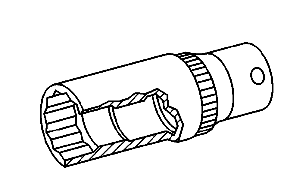


001 589 65 09 00
Socket wrench bit
112 589 00 25 00
Application gun
116 589 01 34 00
Threaded bolt
116 589 20 33 00
Impact extractor
Henviste dokumenter
- ah0130p100004rx Oplysninger om påføring af tætningsmiddel på toppakning
- ah2000n208001a Oplysninger om kølervæske
- ah5400p000101a Oplysninger med henblik på at undgå skader på elektroniske komponenter på grund af elektrostatisk afladning
- ah5410p000101a
- ah5410p000101a Oplysninger om batterier
- ap1800p0101pit Motorolie- og oliefilterskift
- ap1800p0101sx Motorolie- og oliefilterskift
- ap1800p0101sxi Motorolie- og oliefilterskift
- ar0100p005001a
- ar0120p5014tt
- ar0120p5014tt
- ar0120p5014ty
- ar0120p5014ty
- ar0130p5700tt
- ar0130p580003va
- ar0130p580004v
- ar0130p580007sx
- ar0130p580007va
- ar0510p7800ts
- ar0510p7800vb
- ar0520p601001vb
- ar0520p6010ts
- ar0520p7201ts
- ar0708p7008ts
- ar0708p7008tx
- ar0708p7008txx
- ar0910p1150ts
- ar0920p1961ts
- ar0920p1961tx
- ar1320p0001ts
- ar1430p7200ts Af-, påmontering af luftfrakoblingsventil
- ar1430p7251ts Af- påmontering af luftpumpe
- ar1512p2003ts
- ar1512p2003ts Af-, påmontering af tændspoler
- ar1540p5032ts Af-, påmontering af generator
- ar2000p1010ts
- ar2000p1142ts
- ar5410p0003t Afbrydelse, tilslutning af batteriets stelledning
- ar5410p0003t
- ar5410p0003ta Afbrydelse, tilslutning af batteriets stelledning
- ar5410p0003ta
- ar5410p0003tx Afbrydelse, tilslutning af batteriets stelledning
- ar6120p1105t
- ar6120p1105tx
- as0000z000501a Fare for ulykke ved automatisk igangsætning når motoren kører. Fare for personskade på grund af knusning og forbrænding, hvis der arbejdes mens motoren startes eller kører