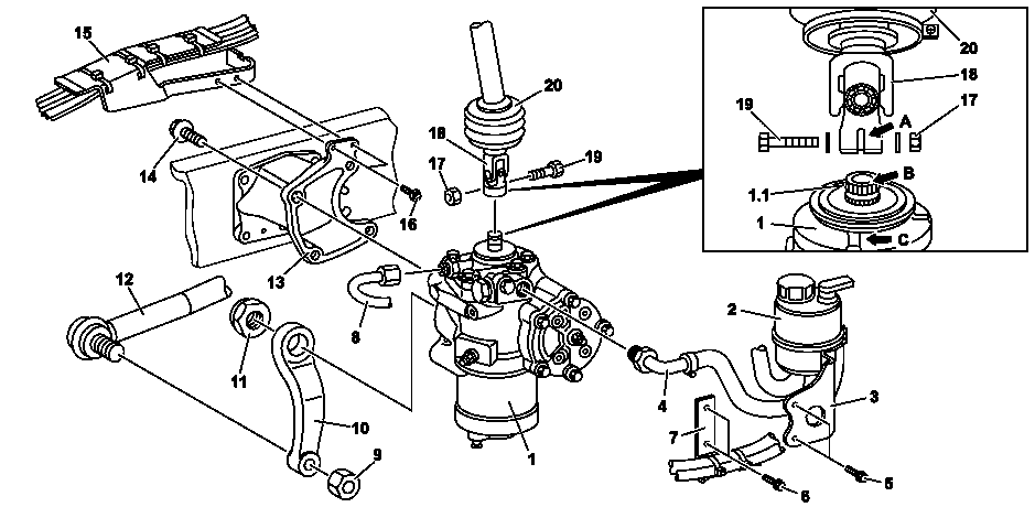
W46.20-1054-09
1 | Steering gear | 8 | Oil pressure line | 16 | Screw | ||
1.1 | Primary shaft | 9 | Nut | 17 | Nut | ||
2 | Oil reservoir | 10 | Pitman arm | 18 | Universal joint | ||
3 | Bracket | 11 | Nut | 19 | Screw | ||
4 | Oil return line | 12 | Drag link | 20 | Boot | ||
5 | Screw | 13 | Steering bracket | A | Assembly slot | ||
6 | Screw | 14 | Screw | B | Mark | ||
7 | Bracket | 15 | Bracket | C | Mark |
Warning | Risk of injury to skin or eyes from hydraulic fluid spraying out under pressure.Risk of poisoning from swallowing hydraulic fluid. | Depressurize hydraulic system completely before starting any work on it. Wear protective clothing and safety glasses. | |
Warning | Risk of injury from being trapped in the swivel range of steered axles | Ensure that no persons or objects are in the swivel range of all steered axles when turning the steering wheel. Do not stand in the swivel range of the additional steering axle when the engine is running. | |
Warning | Risk of injury caused by body parts being pinched or crushed as cab is tilted | Ensure that no one is within the tilting range of the cab as it is being tilted. Always tilt the cab all the way to the end position and secure it with the safety strut. | |
Topical note | Notes on self-locking nuts and bolts | ||
Topical note | Notes on maintenance and repair work | ||
Topical note | Notes on tilting the cab | ||
Note on calculation of tightening torque when using insertion or socket tools with various effective lengths | |||
Notes on safety-relevant components | |||
Notes on hydraulic fluid as per specification Sheet 345.0 | |||
Assessment of steering after accidents | |||
| Remove | ||
1 | Fix holding device for loosening and tightening pitman arm (10) in place under a rear wheel on driver's side. | Only when replacing the steering gear (1) or Pitman arm (10). | |
To fix the vehicle in place, drive the corresponding rear wheel onto the holding device. | |||
Holding device | |||
2.1 | Turn steering full lock to the right. | Left-hand drive vehicle | |
2.2 | Turn steering full lock to the left. | Right-hand drive vehicle | |
3 | Open maintenance flap. | ||
4 | Tilt cab. | ||
5 | Loosen nut (9). | | |
Counterhold the ball joint with an Allen wrench if necessary. | |||
6 | Pry off drag link (12) from pitman arm (10). | The drag link (12) detaches suddenly. | |
Puller | |||
7 | Remove nut (9) and remove drag link (12) from pitman arm (10). | ||
8 | Detach boot (20) from steering gear (1) and slide upward. | ||
9 | Move steering gear (1) to center position. | ||
To do so, turn steering all the way to the left or right. While doing this, determine the number of turns on the steering shaft. Then turn the steering back by half the number of turns and align primary shaft (1.1) with steering gear (1) so that the marks (B and C) line up. | |||
10 | Secure steering wheel against turning. | Fix the steering wheel in place on the support rod using e.g. cable ties. Before securing, make sure that the steering gear (1) is still at the center position. | |
11 | Check marking (B) on primary shaft (1.1) relative to assembly slot (A) of lower universal joint (18). | If assembly slot (A) has moved, | |
| |||
Mark installation position of lower universal joint (18) relative to primary shaft (1.1). | |||
12 | Detach steering shaft with universal joint (18) from steering gear (1) and fasten at the side. | ||
13 | Detach oil pressure line (8) and oil return feed line (4) from steering gear (1). | ||
| Modified steering gear | Only model 930, 932, 933, 934 | |
Counterhold fitting of oil pressure line (8) at steering gear (1). | |||
Plug | |||
14 | Detach oil container (2) with holder (3) from steering gear (1) and fasten at the side. | ||
15 | Detach holders (7, 15) with lines. | ||
16 | Attach lifting belt to steering gear (1). | | |
17 | Using suitable lifting gear, detach steering gear (1) from steering bracket (13) and place on floor or suitable tool cart. | Box wrench | |
18 | Detach pitman arm (10) from steering gear (1). | Only when replacing the steering gear (1) or Pitman arm (10). | |
The Pitman arm (10) detaches suddenly when it is pulled off. | |||
Lifting device | |||
Holding device | |||
Puller | |||
| Install | ||
19 | Attach pitman arm (10) to steering gear (1). | Only when replacing the steering gear (1) or Pitman arm (10). | |
Make sure that the Pitman arm (10) is positioned correctly relative to the Pitman arm shaft. | |||
Nut, steering gear pitman arm to steering gear | |||
Lifting device | |||
Holding device | |||
20 | Attach steering gear (1) to steering bracket (13). | Bolt/nut, steering gear to steering bracket | |
Box wrench | |||
21 | Detach lifting belt from steering gear (1). | ||
22 | Attach holders (7, 15) with lines. | ||
23 | Attach oil container (2) with holder (3) to steering gear (1). | Bolt, bracket for oil reservoir to steering gear | |
24 | Remove all stop plugs. | ||
25 | Install new fittings for oil return feed line (4) and oil pressure line (8) into steering gear (1). | Only when replacing the steering gear (1). | |
Elbow fitting, hose connection for return hose to steering gear | |||
Oil pressure line fitting to steering gear | |||
26 | Attach oil pressure line (8) and oil return feed line (4) to steering gear (1). | Counterhold fitting of oil pressure line (8) at steering gear (1). | |
Union nut, steering gear oil line/hose | |||
27 | Move steering gear (1) to center position. | ||
If necessary, turn primary shaft (1.1) all the way once to the left or right up to the end stop. Then turn primary shaft (1.1) all the way in the opposite direction and count the number of turns while doing so. Finally, turn primary shaft (1.1) back by half the number of turns and align with steering gear (1) so that the marks (B and C) line up. | |||
Adapter kit | |||
28 | Attach steering shaft with universal joint (18) to steering gear (1). | The contact surface for the screw and nut at the lower universal joint (18) must be free of grease. Pay attention to installation position. | |
Fit bolt/nut, universal/constant velocity joint | |||
29 | Detach anti-twist lock from steering wheel. | ||
30.1 | Turn steering to right. | Left-hand drive vehicle | |
30.2 | Turn the steering to the left. | Right-hand drive vehicle | |
31 | Attach drag link (12) to pitman arm (10). | Use new nut (9). | |
Nut, drag link to steering gear pitman arm | |||
32 | Attach boot (20) to steering gear (1). | ||
33 | Bleed steering. | ||
34 | Connect diagnostic system, start XENTRY and perform quick test. | Only on model 934 with code BB7 (Stability control (SR)) | |
35 | Check parameter for steering ratio and adapt if necessary. | Only on model 934 with code BB7 (Stability control (SR)) | |
The parameter for the steering ratio can be checked or adapted under: | |||
36 | End XENTRY and remove the diagnostic system. | Only on model 934 with code BB7 (Stability control (SR)) | |
37 | Conduct a road test. | | |
During the road test check the overall steering behavior of the vehicle. | |||
38 | Checking power steering for leaks. | Visual inspection. |


655 589 00 35 00
Puller
964 589 00 40 00
Holding device
963 589 01 91 00
Plug
964 589 02 59 00
Lifting device


765 589 01 03 00
Box wrench
964 589 00 09 00
Adapter kit
625 589 00 35 00
Puller