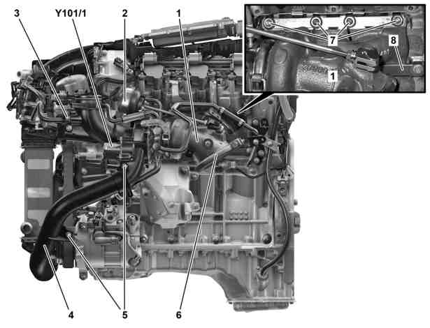
Shown on left ATL |
1 | ATL |
2 | Vacuum unit |
3 | Screw/bolt |
4 | Charge air pipe |
5 | Screw/bolts |
6 | Clamp |
7 | Nuts |
8 | Terminal rail |
Y101/1 | Left divert air switchover valve |
P14.10-2135-06
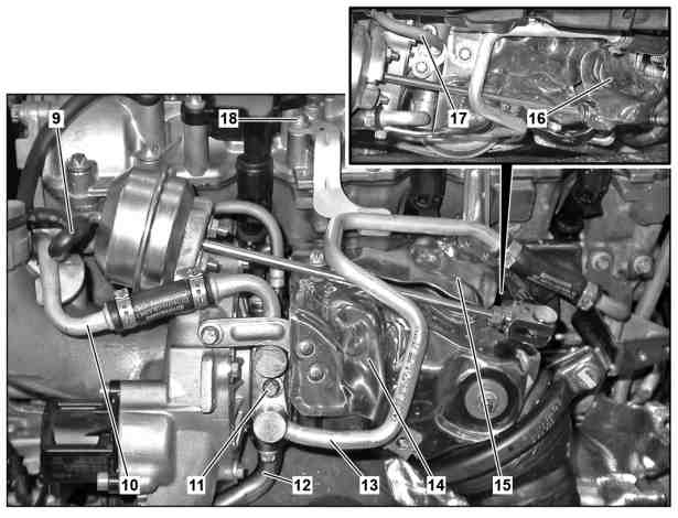
Shown on left ATL |
9 | Vacuum hose |
10 | Coolant return line |
11 | Screw/bolt |
12 | Oil return line |
13 | Coolant feed pipe |
14 | Heat shield |
15 | Heat shield |
16 | Heat shield |
17 | Oil feed line |
18 | Screw/bolt |
P14.10-2136-06
Danger ! | Risk of injury to skin and eyes due to handling of engine oil. Risk of poisoning caused by swallowing engine oil | Wear protective gloves, protective clothing and safety glasses. | |
Danger ! | Risk of injury. Skin or eye injuries may result when handling hot or glowing objects. | Wear protective gloves, protective clothing and safety glasses, if necessary. | |
| Remove/install | ||
1 | Drain off coolant | MODEL 212, 218 with ENGINE 276.8 | |
MODEL 207 with ENGINE 276.8 | |||
2 | Remove upper engine cover | ||
3 | Remove air filter housing on the left or right | ||
4 | Remove insulation of rail on the left or right | Installation: Ensure correct seating of the retaining clamps and the insulation at the rail. | |
5 | Remove screw/bolt (3), detach line and place to one side | Installation: Replace sealing ring. | |
6 | Remove charge air pipe (4) | ||
7 | Disconnect electrical connection at left divert air switchover valve (Y101/1) or on right divert air switchover valve | ||
8 | Remove heat shields (14, 15, 16) from ATL (1) | ||
9.1 | Remove screw/bolts (11, 18) and place coolant feed pipe (13) to one side | ENGINE 276.8 in MODEL 207, 212, 218 | |
Installation: Replace seal. | |||
Bolt, coolant feed/return line to turbocharger | |||
9.2 | Remove screw/bolt (11) and place coolant feed pipe (13) to one side | ENGINE 276.8 in MODEL 207, 212, 218 | |
Installation: Replace seal. | |||
Bolt, coolant feed/return line to turbocharger | |||
10 | Detach coolant return line (10) on ATL (1) | ||
Installation: Replace seal. | |||
11 | Detach holder for coolant return line (10) | ||
12 | Disconnect Electrical connection on ABC hydraulic pump | ENGINE 276.8 in MODEL 207 | |
13 | Set coolant return line (10) aside | ||
14 | Detach CAT bracket at transmission | Bolt, exhaust system bracket to transmission | |
15 | Remove both catalytic converters | ENGINE 276.8 in MODEL 212, 218 | |
16 | Detach EGR line at ATL (1) | ENGINE 276.8 in MODEL 207, 212, 218 | |
17 | Detach oil feed line (17) at ATL (1) | ||
18.1 | Detach oil return line (12) at ATL (1) | When removing the right ATL (1) | |
18.2 | Open clamp on oil return line hose (12) | When removing the left ATL (1) | |
19 | Detach vacuum hose (9) at vacuum unit (2) | ||
20 | Detach coolant expansion reservoir and place with attached hoses and lines to one side | When removing the right ATL (1) | |
ENGINE 276.8 in MODEL 212, 218 | |||
ENGINE 276.8 in MODEL 207 | |||
21.1 | Remove camshaft Hall sensor | When removing the right ATL (1) | |
ENGINE 276.8 in MODEL 212, 218 | |||
ENGINE 276.8 in MODEL 207 | |||
21.2 | Disconnect refrigerant line at expansion valve connecting point | When removing the left ATL (1) | |
22 | Open clamp (6) and disconnect flange connection between ATL (1) and exhaust pipe | Installation: The dowel pin on hot end must be set in the notch on the ATL (1). After screwing down the clamp (6) using the prescribed torque there should be no further gap on the clamp lock. | |
Installation: Replace clamp (6) and seal. | |||
Bolt, pipe clamp to exhaust gas turbocharger | |||
23 | Unscrew nuts (7) for ATL (1) on cylinder head and remove peg board | Installation: Tighten nuts (7) from the inside to the outside. | |
Nut, turbocharger peg board to cylinder head | |||
24 | Unclip ATL (1) from terminal rail (8) and remove upwards | Installation: Replace seal. | |
25 | Install in the reverse order | ||
26.1 | Check oil level in engine and correct if necessary | When reusing the ATL (1) | |
| |||
26.2 | Carry out engine oil and filter change | Only when replacing the ATL (1) | |
| |||
Danger ! | Risk of accident from vehicle starting off by itself when engine running. Risk of injury (bruises and burns) resulting from working on the engine while it is being started or when it is running. | Secure vehicle to prevent it from starting off by itself. Wear closed and snug-fitting work clothes. Do not touch hot or rotating parts. | |
27 | Perform an engine test run and check engine for leaktightness |