GF09.00-P-2000AK | Turbocharging, function | 28.4.04 |
ENGINE 640.940 in MODEL 169, 245.2 up to Model Year 8
ENGINE 640.941 in MODEL 169, 245.2 up to Model Year 8
ENGINE 640.942 in MODEL 169 up to Model Year 8
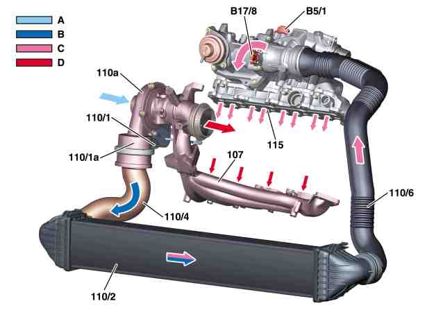
P09.00-2052-76
107 Exhaust manifold
110 A Turbocharger (wastegate)
110/1 Boost pressure control vacuum unit
110/1A Pulsation damper
110/2 Charge air cooler
110/4 Charge air pipe to charge air cooler
110/6 Charge air pipe to mixing tube
115 Intake port
B5/1 Charge pressure sensor
B17/8 Charge air temperature sensor
A Fresh air
B Compressed charge air
C Cooled charge air
D Exhaust
The cylinder charging efficiency is improved as a result of charging. As a result the engine torque and power output are boosted.
When charging, the flow energy of the exhaust gases are used to drive the turbocharger.
The turbocharger draws in fresh air at the compressor inlet and passes this via the compressor outlet and the charge air pipe to the charge air cooler.
The high speed of the compressor turbine wheel and the resultant high volume flow compresses the air in the charge air pipe.
The pulsation damper at the compressor outlet dampens boost pressure fluctuations that arise due to rapid speed changes.
The charge air cooler then cools down the charge air heated by compression and passes the air on via the charge air pipe to the mixing tube. From the mixing tube, the charge air is then passed via the individual intake ducts.
The boost pressure is detected by the boost pressure sensor and the charge air temperature by the charge air temperature sensor and sent in the form of voltage signals to the CDI control unit (N3/9).
Связанные документы
- gf0704p6050ak Датчик температуры нагнетаемого воздуха: конструктивное описание
- gf0704p6051ak Датчик давления наддува: конструктивное описание
- gf0716p6000ak Блок управления CDI: конструктивное описание
- gf0940p4010ak
- gf0941p5000ak