
6 | Leak oil line |
22 | Fuel injector |
A | Leak oil line connection not locked |
B | Leak oil line connection locked |
P07.16-4136-04

P07.16-4135-07
Shown on engine 651.911 |
1 | Electrical connector | 4 | Sealing ring | |
2 | Screw | 22 | Fuel injector | |
3 | Clamping claw |
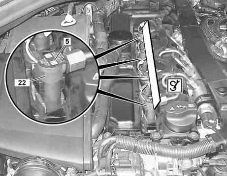
Shown on engine 651.980 |
5 | Identification plate |
22 | Fuel injector |
P07.16-4137-11
Danger | Risk of explosion caused by fuel igniting, risk of poisoning caused by inhaling and swallowing fuel as well as risk of injury to eyes and skin caused by contactwith fuel. | No fires, sparks, open flames or smoking. Pour fuels into suitable and appropriately marked containers only. | |
Danger | Risk of explosion caused by fuel igniting. Risk of injury to skin and eyes caused by fuel spraying out at high pressure | Keep all ignition sources out of hazard area. | |
Notes about Common-Rail components | |||
| Remove/install | ||
1 | Engine cover; remove thread repair for clamping claw mount | ||
2 | Unlock locks for leak oil line connections and detach leak oil line (6) at fuel injectors (22) | Catch fuel coming out with a lint-free clean dry cloth. | |
Installation: Wet the sealing rings for the leak oil line connections with lubricant. | |||
Observe lock for leak oil line connection: in the locked condition a white marking (arrow) is visible is visible (picture B). The white marking (arrow) is not visible (picture A) in a not locked condition . | |||
Special lubricant | |||
3 | Check sealing rings of the leak oil line connections | If sealing rings are damaged | |
| |||
Replace leak oil line | |||
4 | Release and disconnect electrical connection (1) at fuel injectors (22) | Installation: Replace sealing rings and housing cover on the electrical connections (1). | |
Press safety catch with needle nose pliers together. | |||
5 | Remove injection lines between rail and fuel injectors (22) | ||
6 | Remove screw/bolts (2) | Installation: Replace screw/bolts (2) and tighten in stages. Determine the difference in height using a straight edge through simultaneous placing on of the identification plate (5). In this way one can ensure that the fuel injectors (22) are installed correctly. For differences in height of the fuel injectors (22) a sealing ring (4) is missing or there is one sealing ring (4) too many installed. | |
Screw/bolt, clamping claw to injector | |||
Straightedge | |||
7 | Check threaded bush and thread on screw/bolts (2) | For a loosened threaded bush or damaged thread | |
| |||
Replace threaded bushes | |||
Threaded insert for bolt, clamping claw to cylinder head | |||
Mounting adhesive, Loctite 648 | |||
Loctite 7063 (400 ml) cleaning spray | |||
8 | Remove clamping claw (3) | ||
9 | Mark fuel injectors (22) | Installation: in order to assign the fuel injectors (22) to the respective cylinders. | |
10 | Remove fuel injectors (22) | | |
Installation: Replace seals (4). Coat stem of the fuel injectors (22) with special grease. | |||
Special grease | |||
In case of stuck fuel injectors (22) | |||
| |||
Remove fuel injectors | |||
Engine 651 in model 205In case of Bosch injectors | |||
Engine 651 in model 205In case of Delphi injectors | |||
Impact extractor | |||
11 | Close off connections at fuel injectors (22) with a suitable grommet | The grommets are available as an replacement part of the fuel injection system; see EPC Group 07. Multiple use of the grommet is not permitted. Ensure scrupulous cleanliness! | |
| Clean | ||
12.1 | Clean fuel injectors (22) and fuel injector shafts with a round wire brush | In case of light carbonization. | |
| |||
Round brush | |||
12.2 | Clean fuel injectors (22) and fuel injector wells using a round and cylinder brush | In a case of strong carbonization. | |
| |||
Round brush | |||
Cylinder brush | |||
13 | Install in the reverse order | ||
14 | Connect diagnostic system, read out fault memory and perform a control unit adaptation | For replacement of one or more fuel injectors (22). | |
| |||
For new fuel injectors (22) a control unit adaptation must take place in order to store the "IMA coding" in the CDI control unit. Make adhesive label with respective "IQC coding" illegible on the vehicle. | |||
Warning | Risk of accident from vehicle starting off by itself when engine running. Risk of injury (bruises and burns) resulting from working on the engine while it is being started or when it is running. | Secure vehicle to prevent it from starting off by itself. Wear closed and snug-fitting work clothes. Do not touch hot or rotating parts. | |
15 | Carry out an engine test run and check fuel injection systems for leaktightness |


668 589 00 68 00
Cylinder brush
452 589 01 99 24
Straightedge
651 589 01 68 00
Round brush
602 589 00 33 00
Impact extractor


642 589 01 33 00
Threaded adapter
611 589 00 68 00
Round brush
651 589 00 33 00
Extraction claw
Documente menționate
- ad0000p200004b
- ah0716p000201tx Indicaţii componente Common-Rail
- ar0703p9105cd Demontare, montare conductă retur combustibil la injectoare
- ar0716p100003cd Demontarea injectoarelor de carburant blocate
- ar0716p100007rf Înlocuire bucşă filetată injector
- ar0716p1080old
- as0000z000501a Pericol de accident prin pornirea de pe loc cu motorul aflat în funcţionare. Pericol de rănire prin striviri şi arsuri la manipularea în timpul pornirii motorului sau cu motorul aflat în funcţionare
- as0716z000101a Pericol de explozie prin aprinderea carburantului. Pericol de rănire a pielii şiochilor datorită jetului de combustibil care se scurge
- as4700z000101a Pericol de explozie prin aprindere, pericol de intoxicare prin inhalare şi înghiţire de carburant cât şi pericol de rănire prin contactul pielii şi ochilor cu carburantul