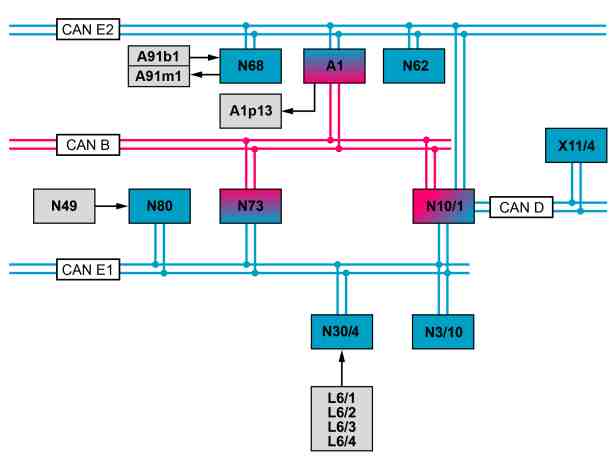
P46.35-2075-76
A1 Instrument cluster
A1p13 Multifunction display
A91b1 Electric power steering torque sensor
A91m1 Electric power steering actuator motor
CAN B Interior CAN
CAN D Diagnostic CAN
CAN E1 Chassis CAN 1
CAN E2 Chassis CAN 2
L6/1 Left front axle speed sensor
L6/2 Right front axle speed sensor
L6/3 Left rear axle speed sensor
L6/4 Right rear axle speed sensor
N3/10 ME-SFI [ME] control unit
N10/1 Front SAM control unit with fuse and relay module
N30/4 Electronic Stability Program control unit
N49 Steering wheel angle sensor
N62 Parking system control unit (with code (220) PARKTRONIC or with code (235) Active Parking Assist)
N68 Electrical power steering control unit
N73 Electronic ignition switch control unit
N80 Steering column module control unit
X11/4 Diagnostic connector
Function requirements, general
Status "Circuit 15 ON"
The "Circuit 15 ON" status is sent by the electronic ignition lock control unit over the chassis CAN 1 and chassis CAN 2 with the front SAM control unit with fuse and relay module interface to the electrical power steering control unit. The engine rpm is sent by the electrical power steering control unit over the chassis CAN 1 and chassis CAN 2 with the front SAM control unit with fuse and relay module interface by the ME-SFI [ME] control unit.
Electric power steering (ES), general
The ES consists of the rack-and-pinion steering gear, the electric power steering torque sensor, the electric power steering actuator motor and the electrical power steering control unit. The ES performs stepless, speed-dependent regulation of the power steering.
-----------------------------------------------------------------------------------------
The advantages compared to hydraulic power steering are:
- Improved steering feel
- Fuel saving
- Hydraulic fluid not required
- Compact design
- Speed-dependent steering servo
- Steering return is assisted
- Diagnosis capability
System diagnosis is conducted over the chassis CAN 2, the front SAM control unit with fuse and relay module, the diagnostic CAN and the diagnostic connector with the aid of Xentry Diagnostics.
The ES comprises the following subfunctions:
Power steering function sequence
Steering assistance function sequence
Function sequence for reducing holding torque
Function sequence for limp-home mode
Display on instrument cluster function sequence
-----------------------------------------------------------------------------------------
Power steering function sequence
The electrical power steering control unit requires the following information to calculate the steering power assistance required:
- Current steering moment, from electric power steering torque sensor
- Current wheel speeds, determined through left front axle rpm sensor, right front axle rpm sensor, left rear axle rpm sensor and right rear axle rpm sensor, and sent over chassis CAN 1 and chassis CAN 2 with the front SAM control unit with fuse and relay module interface by the Electronic Stability Program control unit
- Steering wheel angle and steering speed, over chassis CAN 1 and chassis CAN 2 with front SAM control unit with fuse and relay module interface from steering wheel angle sensor in steering column tube module control unit
-----------------------------------------------------------------------------------------
- Current engine speed > 400 rpm, over chassis CAN 1 and chassis CAN 2 with front SAM control unit with fuse and relay module interface from ME-SFI [ME] control unit
The electric power steering control unit uses this information to calculate the steering force support to be applied from the stored characteristics map and activates the electric power steering actuator motor accordingly.
The direction of rotation of the electric power steering actuator motor depends on the direction of movement of the steering wheel.
The steering force assistance is transmitted from the electric power steering actuator motor to the rack-and-pinion steering gear, thereby supporting the steering moment applied by the driver.
-----------------------------------------------------------------------------------------
When the vehicle is at a standstill, no steering force support is available if the engine and ignition are switched off With the ECO Start-Stop function, reduced steering force support is available when the vehicle is at a standstill if the engine was switched off via the ECO start/stop function. The steering force support is deactivated after the ignition is switched off. Steering force assistance is active if the vehicle is maneuvered when the engine is off and the ignition is switched on.
Steering assistance function sequence
The steering assistance function helps the driver to achieve an optimum steering reaction in critical driving situations. Steering assistance is provided with the aid of the electric power steering control unit and Electronic Stability Program control unit.
-----------------------------------------------------------------------------------------
The following functions are performed here:
- Driver support through countersteering for a vehicle with oversteer
- Driver support for braking on varying road surfaces
The current vehicle status is sensed by the Electronic Stability Program control unit.
If necessary, the "steering assistance torque request" message is sent over the chassis CAN 1 and chassis CAN 2 with the front SAM control unit with fuse and relay module interface to the electrical power steering control unit, which actuates the electric power steering actuator motor.
-----------------------------------------------------------------------------------------
During a parking procedure the parking system control unit (with code (220) PARKTRONIC or code (235) Active Parking Assist) sends the following signals over the chassis CAN 2 to the electrical power steering control unit:
- Current status of parking system control unit
- Vehicle stop signal, at which the vehicle stops at a maneuver point during the parking process
- Requested toothed rack position
The following signals are sent by the electrical power steering control unit to the parking system control unit (with code (220) PARKTRONIC or with code (235) Active Parking Assist):
- Current status of the electrical power steering control unit
-----------------------------------------------------------------------------------------
Function sequence for reducing holding torque
If a holding torque is applied by the driver when driving the vehicle straight ahead, e.g. for a crosswind or on a road surface inclined on one side, the electrical power steering control unit detects it. The applied holding torque is partially compensated for by the electric power steering.
To rule out any faulty compensation (e.g. highway corner with large radius), the electrical power steering control unit receives the rotational speed (vehicle speed about the vertical axis) and the vehicle's lateral acceleration over chassis CAN 2 and chassis CAN 1 with the front SAM control unit with fuse and relay module interface from the Electronic Stability Program control unit.
The reduction of the vehicle's holding torque depends on the speed.
-----------------------------------------------------------------------------------------
Function sequence for limp-home mode
When the ES is switched on (via "circuit 15 ON"), the electric power steering control unit carries out a self-test. If a fault is detected, the steering force assistance is not switched on. The vehicle can be steered with increased force of the hand.
During driving operation, the electrical power steering control unit checks the signals from the electric power steering torque sensor. If these signals are outside the defined upper or lower limit, the ES is switched off by the electrical power steering control unit. The vehicle can be steered with increased force of the hand.
Display on instrument cluster function sequence
The electrical power steering control unit control unit transmits the request for a warning message via chassis CAN 2 to the instrument cluster.
The instrument cluster's multifunction display then shows the warning message "Power steering defective! Visit workshop!".
Powiązane dokumenty
- gf4635p9997rk Zestawienie przeglądowe elementów systemowych elektrycznego wspomagania przekładni kierowniczej (ES)
- pe4635p205097rka