AR07.12-S-8410A | Removing and installing injection pump | 4.12.95 |
ENGINE 601 in MODEL 638.064 /074 /164 /174 /274

S07.11-2001-09
1 Connecting rod
2 Throttle control lever
3 Bracket
4 Connection piece
5 Leak fuel line
6 Return flow fuel line
7 Vacuum line
8 Engine stop vacuum unit
9 Fuel lines
X114 Immobilizer connector (code FZ6)
Y30 Electronic blocking valve (code FZ6)

S07.11-2002-09
1 Connecting rod
10 Chain tensioner
11 Central securing bolt Left-hand thread
12 Washer
13 Disk spring
14 Centering sleeve
15 Bolt
16 Serrated wrench
17 BCAPC unit (engine 601.970)
18 Vacuum line (engine 601.970)
19 PISI vacuum unit
20 Vacuum line
21 Bolt
22 Support
23 Seal
24 Four-point nut
25 Washer
26 Injection pump
27 Seal
28 Screw plug
29 Blocking bolt
X120 ISC connector
Y56 ISC solenoid


S07.11-2508-01
30 Plug connection
31 Vacuum control valve
S70 Microswitch
32 Plug connection
S07.11-2509-01
| Removing | ||
1 | Remove radiator | ||
2 | Remove vacuum pump | ||
3 | Remove dipstick guide tube | ||
4 | Remove oil filter element | Allow oil to flow out of oil filter housing | |
5 | Remove oil filter housing with oil-water heat exchanger attached | Collect oil which flows out | |
6 | Position engine to 15° after TDC of cylinder 1 | Rotate engine at crankshaft | |
7 | Detach connecting rod (1) at throttle control lever (2) | ||
8 | Detach fuel lines (9) at fuel filter | Inspect seals, replace if necessary. Collect fuel which flows out | |
9 | Detach leak fuel line (5) and return flow fuel line (6) at connection piece (4) | ||
10 | Detach vacuum line (7) at engine stop vacuum unit (8) | ||
11.1 | Separate vacuum hoses from vacuum control valve (31) | Engine 601.942 with code MS5 (low emission engine stage II) or KD1 (emissions control system (oxidation cat.) up to 01.07.96) | |
12.1 | Unplug connector (32) | Engine 601.970 with code MS5 (low emission engine stage II) | |
13 | Separate plug connection (X114) at the electronic blocking valve (Y30) | With code FZ6 (immobilizer) | |
14.1 | Separate plug connection (30) from microswitch (S70) | Engine 601.942 with code MS5 (low emission engine stage II) or KD1 (emissions control system (oxidation cat.) up to 01.07.96) | |
15 | Detach injection lines at the injection pump | Do not bend injection lines | |
16 | Detach vacuum line (18) at charge pressure unit (17) | Engine 601.970 | |
17.1 | Detach vacuum line (20) at the PISI vacuum unit (19) | On engines with PISI | |
17.2 | Separate plug connection (X120) at the ISC solenoid (Y56) | On engines with ISC (electronic idle speed control) | |
18 | Unscrew bolt (21) at support (22) | | |
19 | Install centering sleeve (14) | | |
20 | Unscrew central bolt (11) and take off together with washer (12) and disk spring (13) | Left-hand thread Counterhold crankshaft if necessary | |
21 | Remove chain tensioner (10) | ||
22 | Unscrew bolts (15) at injection pump flange and take off together with four-point nuts (24) | Bolt (15) cannot be removed (arrow) Top bolt (15) can be removed by raising engine | |
23 | Remove injection pump (26) | Counterhold injection timing device | |
24 | Detach connecting rod (1) at adjusting lever of injection pump | ||
25 | Detach fuel lines of injection pump | Release quick locks | |
| Installing | ||
26 | Fit on fuel lines of injection pump | Inspect seals, replace if necessary and secure quick locks | |
| |||
27 | Block injection pump (26) before installing | Blocking bolt (29) must be felt to engage. Pay attention to distance (arrow) between collar of stud and bolt | |
| |||
| |||
handtight | |||
| Check whether engine is at 15° after TDC of cylinder 1, correct if necessary | Rotate engine only in direction of rotation with centering sleeve (14) installed | |
28 | Insert injection pump (26) and bolt tight to flange | Replace seal (23) and oil with engine oil | |
| |||
29 | Remove blocking bolt (29) and insert screw plug (28) | Otherwise injection pump will be damaged when starting | |
| |||
30 | Install chain tensioner (10) | Replace seal | |
31 | Tighten central bolt (11) with washer (12) and disk spring (13) | Left-hand thread | |
| |||
32 | Remove centering sleeve (14) | ||
33 | Install connecting rod (1) | Pay attention to installation position | |
34 | Fit remaining parts to vehicle | Injection system bled automatically | |
35 | Check start of delivery | Position sensor GIM method | |
or | |||
digital tester GIM method | |||
36 | Check idle speed, set if necessary | ||
37 | Inspect for leaks |
Diesel injection system, general
Number | Designation | Engine 601.942 601.970 | |
BA07.11-N-1005-01A | Injection pump to support | Nm | 23 |
BA07.11-N-1007-01A | Injection pump to crankcase | Nm | 23 |
BA07.11-N-1008-01A | Central bolt of injection timing device to injection pump Left-hand thread | Nm | 46 |
BA07.11-N-1009-01A | Screw plug to governor housing | Nm | 30 |
BA07.11-N-1011-01A | Return flow line to injection pump | Nm | 13 |
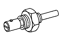

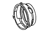
601 589 05 21 00
601 589 00 08 00
601 589 05 14 00
Blocking bolt
Centering sleeve
Serrated wrench
Powiązane dokumenty
- ap1800d0101a Wymiana oleju silnikowego i filtra oleju
- ar0100s0120b
- ar0145s9600b
- ar0510s7800b
- ar0711s2053a
- ar0711s8240a
- ar0711s8244a
- ar0711s841001a
- ar0711s841002a
- ar0712s9230a
- ar1820s3471a
- ar2020s3865b
- ar4305s1320a
- ar4720s5510a