
D05.20-1104-09
1 | Intake camshaft | 5 | Chain tensioner | A | Locking bore | ||
2 | Exhaust camshaft | 6 | Front cover | B | Alignment bores | ||
3 | Retaining pin | 7 | Slide rail | ||||
4 | Cylinder head cover | 8 | Driver |
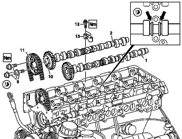
1 | Intake camshaft |
2 | Exhaust camshaft |
9 | Bolts |
10 | Dowel pin |
11 | Camshaft sprocket |
12 | Bolts |
13 | Camshaft bearing cap |
D05.20-1112-06
| Remove | ||
1 | Remove cylinder head cover (4) | ||
2 | Position piston of cylinder 1 to ignition TDC | | |
Crank engine clockwise at crankshaft to TDC marking (arrows). | |||
3 | Lock intake camshaft (1) | Insert retaining pin (3) at camshaft bearing cap 1 (13) into locking bore (A) in camshaft sprocket of intake camshaft (1). | |
Retaining pins | |||
4 | Remove front cover (6) at cylinder head | ||
5 | Unscrew driver (8) at intake camshaft (1), remove slide rail (7) | Socket wrench socket 17 mm 6-point 3/8 inch square | |
6 | Remove camshaft sprocket (11) at exhaust camshaft (2) and remove with mounted timing chain | Counterhold exhaust camshaft (2) if necessary with open end wrench. | |
7 | Remove camshaft bearing cap (13) | ||
Topical note | Marking on camshaft bearing caps | ||
8 | Remove intake camshaft (1) and exhaust camshaft (2) | ||
| Install | ||
9 | Insert intake camshaft (1) and exhaust camshaft (2) | ||
| |||
| |||
Mount intake camshaft (1) and exhaust camshaft (2) so that both alignment bores (B) in camshaft sprockets face each other and the markings of intake camshaft (1) and exhaust camshaft (2) and camshaft bearing cap (13) are in alignment (arrows). | |||
Camshaft code numbers | |||
10 | Mount camshaft bearing cap (13) | ||
Topical note | Marking on camshaft bearing caps | ||
Install camshaft bearing cap (13) in reverse order at same location. Tighten bolts (12) evenly in increments of, in each case, | |||
Screw/bolt, camshaft bearing cap to cylinder head | |||
11 | Install camshaft sprocket (11) with mounted timing chain and new bolts (9) on exhaust camshaft (2) | Take into account dowel pin (10). Counterhold exhaust camshaft (2) if necessary with open end wrench. | |
Bolt, camshaft sprocket to exhaust camshaft | |||
12 | Install chain tensioner (5) | ||
13 | Check basic position of camshafts | ||
Where necessary after check | |||
| |||
Correct basic position of camshafts. | |||
14 | Insert slide rail (7), screw driver (8) into intake camshaft (1) | Socket wrench socket 17 mm 6-point 3/8 inch square | |
Bolt, driver to intake camshaft | |||
15 | Install front cover (6) at cylinder head | ||
16 | Install cylinder head cover (4) |

111 589 03 15 00
Retaining pins
Powiązane dokumenty
- ah0520p699204he Oznaczenia pokryw łożysk wałków rozrządu
- ar0120d5014na
- ar0130d5700na
- ar0510d7800na
- ar0520d6010na
- ar0520d6025na
- ar0520d699204na
- bt0520p000201a Zmieniony kształt krzywek wałka rozrządu