


001 589 51 33 00
Hand pump
Hollow piston cylinder
Extraction tool
Hydraulic hose (complete)
611 589 02 33 00
652 589 00 33 21
652 589 00 33 23

D07.16-1286-11
Shown for engines 611.981 and 911.987.
1. Remove screen (1) from turbocharger.
2. Unscrew crankcase ventilation (2) and cover the opening to the cylinder head cover with a shop towel.
Only when the injector for cylinder 1 or 2 is removed.
3. Slacken the engine wiring harness from the cylinder head, remove from rail and pull to the side.
4. Unscrew oil filler cap (3) and cover the opening to the cylinder head cover with a shop towel.
Only when injector for cylinder 1 or 2 is removed.
Only when injector for cylinder 1 is removed for engines 611, 612, 647.
Shown on engine 611

D07.16-1287-01
5. Unscrew solenoid valve (arrow) from the injector.

D07.16-1288-01
6. Press down the anchor plate with a screwdriver and remove the circlip (arrow).
7. Remove the anchor plate and remove the internal components of the injector.

D07.16-1289-02
8. Unscrew the valve tensioning nut in the injector using a hollow bore hexagon socket head screw (4) .
The hollow bore hexagon socket head screw (4) is included in the delivery scope of the extractor tool kit.
9. Remove the anchor pin with anchor washer from the injector.

D07.16-1290-01
10. Screw the threaded insert (5) onto the respective injector finger tight up to the stop.
11. Tighten the union nut (6) for the threaded insert (5) finger-tight to the injector.

D07.16-1291-02
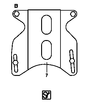
12. Fit the supports to the adapter plate (7) (adapter plate is included in the extractor tool kit).
Depending on which injector is to be removed, the lift support points must be modified.
a. Only engine 611 for injector, cylinder 2.
b. Engine 611 for injector, cylinders 1, 3, and 4 and for engines 612 and 647 for injector cylinder 1 to 5.
D07.16-1292-02

D07.16-1293-01
Shown on engine 611 at injector for cylinder 1
13. Attach the adapter plate (7) with the supports to the screw heads of the cylinder head cover.
Make sure the supports are correctly seated on the screw heads of the cylinder head cover to prevent damage to the cylinder head cover or to the tool.

D07.16-1294-01
14. Screw the hollow piston cylinder (8) with knurled screw (9) onto the threaded insert.
15. Connect the hand pump with the hydraulic hose to the hollow piston cylinder (8)
16. Operate the hand pump and pull out the injector.
If the injector is stuck, release the excess pressure, screw the knurled screw (9) back into the threaded insert and build up the excess pressure once more. Repeat this procedure until it is no longer possible to screw the knurled screw (9) into the threaded insert.
At a pressure buildup of over 350 bar, watch out for deformation of the adapter plate (7).
17. Release pressure.
18. Unscrew the knurled screw (9) from the threaded insert (5) .
19. Remove the hollow piston cylinder.
20. Remove the adapter plate (7).
21. Unscrew the threaded insert (5) from the injector.
If an injector has been removed at an excess pressure of over 350 bar, the cylinder head cover and the cylinder head must be inspected at the support points of the extractor tool for plastic deformation. Remove the cylinder head cover for this purpose.