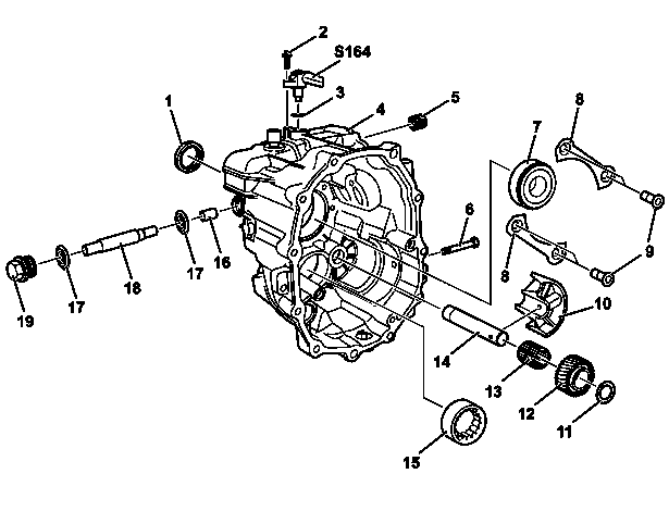
1 | Radial shaft sealing ring |
2 | Screw |
3 | Sealing ring |
4 | Rear section of transmission housing |
5 | Bearing |
6 | Screw |
7 | Bearing |
8 | Locking plates |
9 | Bolts |
10 | Bearing shell |
11 | Thrust plate |
12 | Reverse gear |
13 | Cylindrical roller bearing |
14 | Reverse idler shaft |
15 | Bearing |
16 | Sleeve |
17 | Washers |
18 | Guide pin |
19 | Screw plug |
S164 | Transmission neutral position switch |
D26.40-1176-06
Topical note | Notes on self-locking nuts and bolts | ||
| Remove | ||
1 | Remove hydraulic pump from power take-off | Model 906 with code N05 (Power take-off countershaft (2c) without flange) | |
2 | Remove transmission | ||
3 | Attach transmission to assembly stand | ||
4 | Remove shift shaft | ||
5 | Disassemble transmission housing | ||
6 | Remove main shaft and countershaft with shift unit | ||
| Disassemble | ||
7 | Remove bearing (5) | Unscrew hexagon-insert from counter stay. | |
Internal extractor | |||
Counter stay | |||
8 | Remove radial shaft sealing ring (1) | | |
If seat is damaged | |||
| |||
Replace rear section of transmission housing (4). | |||
9 | Remove tab washers (8) | To do this, remove bolts (9) . | |
10 | Remove bearing (7) | Sleeve | |
11 | Remove reverse idler shaft (12) and reverse idler gear (14) | ||
12 | Remove bearing (15) | Puller, 28-37 mm dia. | |
Counter stay | |||
13 | Remove guide pin (18) and washers (17) | To do so, remove screw plug (19). | |
14 | Remove sleeve (16) | ||
15 | Remove the switch for transmission neutral position (S164) | Unscrew bolt (2) to do this. | |
| Clean | ||
16 | Clean seats and bearing seats | ||
| Assemble | ||
17 | Install transmission neutral position switch (S164) | Replace bolt (2) and sealing ring (3). | |
Screw/bolt, transmission neutral switch | |||
18 | Install new bearing (5) | Drift | |
19 | Install new radial shaft sealing ring (1) up to end stop | ||
| FE manual transmission oil (specification 235.3) | ||
| Gear oils (Sheet 235.10) | ||
Coat sealing lip of radial shaft sealing ring (1) with transmission oil. | |||
Drift | |||
20 | Press in new bearing (7) as far as the end stop | The chamfer on the outer bearing race must point toward the main shaft. | |
Commercially available devices/tools | |||
Drift | |||
21 | Press in bearing (15) to end stop | Commercially available devices/tools | |
Drift | |||
22 | Install tab washers (8) | Replace screw/bolts (9). | |
Screw/bolt, locking plate for countershaft bearing, main shaft bearing or drive shaft bearing to transmission housing | |||
23 | Install reverse idler shaft (14) and reverse idler gear (12) | ||
Mounting bolt, reverse idler shaft to transmission housing | |||
24 | Install sleeve (16) | ||
25 | Install guide pin (18) with washers (17) | Replace screw plug (19). Check condition of washers (17). | |
Screw plug of guide pin | |||
Depending on findings | |||
| |||
Replace washers (17). | |||
| Install | ||
26 | Install main shaft and countershaft with shift unit | ||
27 | Install shift shaft | ||
28 | Assemble transmission housing | ||
29 | Detach transmission from assembly stand | ||
30 | Install transmission | ||
31 | Mount hydraulic pump onto power take-off | Model 906 with code N05 (Power take-off countershaft (2c) without flange) |


000 589 25 33 00
Internal extractor
000 589 28 33 00
Puller, 28-37 mm dia.
716 589 00 15 00
Drift
716 589 01 33 00
Sleeve


711 589 04 15 00
Drift
000 589 33 33 00
Counter stay
711 589 16 15 00
Drift
711 589 06 15 00
Drift
参照文書
- ah0000n000101a セルフロッキング·ナットおよびボルトに関する注意事項
- ar2610d0020h トランスミッションの脱着
- ar2610d0036a トランスミッションをアッセンブリ·マウントに固定します。
- ar2640d2002e トランスミッション·ハウジングの分解、組立て
- ar2650d0002b
- ar2650d200201c リバース·シャフトとリバース·アイドラ·ギヤの脱着
- ar2660d6500a シフト·シャフトの脱着
- bb0040p023503a FE マニュアル・トランスミッション・オイル (仕様 235.3)
- bb0040p023510a ハイポイド·ギヤ·オイル (仕様 235.10)