


651 589 00 99 00
Glow plug repair kit, M8
642 589 01 99 00
Glow plug repair set
642 589 00 99 00
Glow plug repair kit, M8
611 589 00 91 00
Record plug

Shown: glow plug repair kit, M8 642 589 00 99 00 |
1 | Stud extractor |
2 | Drilling-out sleeve |
4a | Screw |
6 | Centering and support pipe |
7 | Bayonet guide |
8 | Graduated drill |
9 | Drill holder |
10 | Thread tap |
11 | Thread tap holder |
12 | Extraction spindle |
13 | Bearing unit |
15 | Thread tap |
16 | Tool holder with ratchet |
17 | Special drill |
18 | Round wire brush |
19 | Round wire brush |
D15.20-1132-06

Shown: glow plug repair kit, M8 651 589 00 99 00 |
20 | Mounting rail |
21 | Mounting angle |
22 | Bolts |
24 | Combination bracket |
25 | Combination bracket |
P15.20-2267-06

Shown: glow plug repair set 642 589 01 99 00 |
2 | Drilling-out sleeve |
8 | Graduated drill |
10 | Thread tap |
12 | Extraction spindle |
15 | Thread tap |
17 | Special drill |
18 | Round wire brush |
19 | Round wire brush |
D15.20-1138-06
Use the following special tools: glow plug repair kit, M8 642 589 00 99 00 and glow plug repair kit, M8 651 589 00 99 00.
For a glow plug thread M10x1 also use: Glow plug repair set 642 589 01 99 00.
After every chip cutting machining operation step immediately suction up the chips created or clean the bores with a round wire brush (18, 19).
Damage may occur on the engine otherwise.
Prepare the glow plug |

1 | Place the stud extractor (1) for a 4 mm dia. on the pin of the cap of the glow plug and tear off the center electrode of the glow plug clockwise. |
Remove all loose parts. |
P15.20-2183-01

2 | Again tear off the center electrode of the glow plug using the stud extractor (1) for a 2.5 mm dia.. |
If the center electrode of the glow plug is broken not on the lower end but rather immediately behind the cap of the electrical connection. |
If renewed tearing off of the center electrode of the glow plug is not possible. | |
| |
Hammer in the drill-out sleeve (2) using a hammer and punch flush into the glow plug. |
The drill-out sleeve (2) is beveled; the arrow on the drill-out sleeve (2) must point to the cylinder head. |
In order to stabilize the center electrode for drilling out. |
For a a glow plug thread M8x1 use a drill-out sleeve (2) with an inside diameter of 2.6 mm. |
If the drill-out sleeve (2) cannot be hammered in flush. | |
| |
Cut off the projecting out part of the drill-out sleeve (2) flush using a side cutting pliers. |
P15.20-2184-01
Attach and align the boring out jig |

3 | Mount the mounting rail (20) with mounting angles (21) and screw/bolts (22, 23) loosely on the cylinder head. |
Use screw/bolts (23) for rail. |
4 | Push mounting rail (20) downwards (arrows) and tighten screw/bolts (23) . |
D15.20-1127-10

5 | Lead the centering and support pipe (6) with the smaller diameter from below into the bayonet guide (7). |
When drilling out glow plug on cylinder 1, 2 or 3. |
P15.20-2244-01

6 | Align centering and support pipe (6) with bayonet guide (7) over the glow plug to be drilled out at the mounting rail (20) and tighten screw/bolt (4a) . |
When drilling out glow plug on cylinder 1, 2 or 3. |
7 | Push the centering and support pipe (6) into the glow plug well (arrow) and center it. |
When drilling out glow plug on cylinder 1, 2 or 3. |
Through turning the combined drilling and extraction device (20) center the centering and support pipe (6) in such a way that it is aligned with the glow plug. |
D15.20-1128-01

8 | Tighten down screw/bolts (22) for the mounting rail (20) . |
When drilling out glow plugs on cylinder 1, 2 or 3. |
After tightening the screw/bolts (22) the centering and support pipe (6) it must still be possible to introduce it into the glow plug well and to pull it out again without special use of force. If not, repeat the centering process. |
P15.20-2247-01
9 | Detach bayonet guide (7) from the mounting rail (20) and remove the centering and support pipe (6). |
When drilling out the glow plug at cylinder 1, 2 or 3. |
10 | Mount bayonet guide (7) on mounting rail (20) and tighten the screw/bolt (4a) . |
D15.20-1128-01
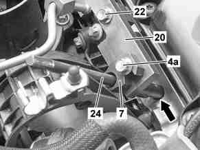
11 | Introduce the combination bracket (24) through the bayonet guide (7) into the glow plug well. |
For drilling out the glow plug on cylinder 4. |
The inscription IN / OUT POSITION on the combination bracket (24) must point upwards. |
12 | Center the combination bracket (24) in the glow plug well (arrow). |
For drilling out the glow plug on cylinder 4. |
Through shifting of the mounting rail (20) center the combination bracket (24) in the bayonet guide (7) in such a way that it is aligned to the glow plug. |
13 | Tighten down both screw/bolts (22) for the mounting rail (20) . |
For drilling out the glow plug on cylinder 4. |
After tightening the screw/bolts (22) it must still be possible to introduce the combination bracket (24) into the glow plug well and to pull it out again without special use of force. If not, repeat the centering process. |
D15.20-1129-01
Redrill glow plug |

14 | Clamp the graduated drill (8) into the combination bracket (24) and lubricate the graduated drill (8) as well as the combination bracket (24). |
For a glow plug thread M8x1 use the graduated drill (8) with an inscription M8. |
P15.20-2253-01

15 | Introduce the combination bracket (24) with graduated drill (8) into the bayonet guide (7). |
On cylinder 4 the inscription IN / OUT POSITION on the combination bracket (24) must point upwards. |
16 | Center and position glow plug 2 to 3 mm deep. |
If a drill-out sleeve (2) was previously stamped in. |
D15.20-1139-02

17 | Clamp the special drill (17) into the combination bracket (24) and lubricate the special drill (17) as well as the combination bracket (24). |
If a drill-out sleeve (2) was previously stamped in. |
For a glow plug thread M8x1 use the special drill (17) with a 4.5 mm dia. |
18 | Drill out the center electrode of the glow plug until the combination bracket (24) almost touches the cylinder head. |
If a drill-out sleeve (2) was previously stamped in. |
D15.20-1140-02
19 | Clamp the graduated drill (8) into the combination bracket (24) and lubricate the graduated drill (8) as well as the combination bracket (24). |
If a drill-out sleeve (2) was previously stamped in. |
For a glow plug thread M8x1 use the graduated drill (8) with an inscription M8. |
P15.20-2253-01

20 | Introduce the combination bracket (24) with graduated drill (8) into the bayonet guide (7). |
On cylinder 4 the inscription IN / OUT POSITION on the combination bracket (24) must point upwards. |
21 | Drill out the glow plug thread in the core up to the marking 1st STOP OM651. |
Through multiple putting down of the graduated drill (8) bore out the glow plug thread at the core until the marking (A) on the combination bracket (24) 1st STOP OM651reaches the upper edge of the bayonet guide (7). |
22 | Remove the combination bracket (24) with graduated drill (8) from the bayonet guide (7). |
On cylinder 4 the inscription IN / OUT POSITION on the combination bracket (24) must point upwards. |
23 | Clean opening. |
P15.20-2256-02

24 | Clamp the thread tap (10) into the combination bracket (25) and lubricate the thread tap (10) as well as the combination bracket (25). |
For a glow plug thread M8x1 use the thread tap (10) with the inscription UNF No. 12. |
P15.20-2257-01

25 | Introduce the combination bracket (25) with thread tap (10) into the bayonet guide (7). |
On cylinder 4 the inscription IN / OUT POSITION on the combination bracket (25) must point upwards. |
26 | Mount the tool holder with ratchet (16) on combination bracket (25) and cut a thread in the glow plug body. |
Cut the thread as a right-hand thread as deep as possible into the glow plug body. Lubricate the thread tap (10) a number of times in the process. |
27 | Remove the thread tap (10) with combination bracket (25) from the bayonet guide (7). |
On cylinder 4 the inscription IN / OUT POSITION on the combination bracket (25) must point upwards. |
28 | Clean opening. |
D15.20-1141-02
29 | Lubricate the combination bracket (24) and the graduated drill (8). |
30 | Introduce the combination bracket (24) with graduated drill (8) into the bayonet guide (7). |
For a glow plug thread M8x1 use the graduated drill (8) with an inscription M8. |
On cylinder 4 the inscription IN / OUT POSITION on the combination bracket (24) must point upwards. |
31 | Bore out the remaining glow plug thread. |
Through multiple application (putting down) of the graduated drill (8) bore out the glow plug thread until the combination bracket (24) almost stands on the cylinder head. |
32 | Remove the combination bracket (24) with graduated drill (8) from the bayonet guide (7). |
On cylinder 4 the inscription IN / OUT POSITION on the combination bracket (24) must point upwards. |
33 | Clean opening. |
D15.20-1139-02
34 | Introduce the combination bracket (25) with thread tap (10) into the bayonet guide (7). |
On cylinder 4 the inscription IN / OUT POSITION on the combination bracket (25) must point upwards. |
35 | Cut the thread further into the glow plug holder. |
Cut the thread as a right-hand thread as deep as possible into the glow plug body. Lubricate the thread tap (10) a number of times in the process. |
36 | Remove the thread tap (10) with combination bracket (25) from the bayonet guide (7). |
On cylinder 4 the inscription IN / OUT POSITION on the combination bracket (25) must point upwards. |
37 | Clean opening. |
D15.20-1141-02

38 | Remove screw/bolt (4a) and detach bayonet guide (7) from the mounting rail (20). |
D15.20-1137-02

39 | Introduce the centering and support pipe (6) with the larger diameter into the glow plug well. |
40 | Screw extraction spindle (12) into the previously cut thread and tighten. |
For a glow plug thread M8x1 use the extraction spindle () with thread UNF No. 12. |
41 | Grease the extraction spindle (12). |
P15.20-2260-02

42 | Screw bearing unit (13) onto the extraction spindle (12). |
43 | Counterhold the extraction spindle (12) and remove the remains of the glow plug () by turning the bearing unit (13). |
Always counterhold the extraction spindle (12) by turning the bearing unit (13)! |
If the extraction is very sluggish | |
| |
Loosen the bearing unit (13) again and carefully tap the end of the extraction spindle (12) with a hammer. |
D15.20-1126-01

44 | Clean glow plug hole with round wire brushes (18, 19) free of soot and deposits. |
For a glow plug thread M8x1 use the round wire brushes (18, 19) with a 7 mm dia. and a 4.2 mm dia. |
P15.20-2194-01
Recut the glow plug thread in the cylinder head |
45 | Insert a stop plug from the set of stop plugs into the glow plug hole. |
46 | Mount bayonet guide (7) with screw/bolt (4a) on mounting rail (20) over the glow plug hole . |
D15.20-1137-02

47 | Clamp the thread tap (15) into the combination bracket (25) and fill the flutes of the thread tap (15) with grease. |
For glow plug thread M8x1 use the thread tap (15) with an inscription M8x1. |
48 | Introduce the combination bracket (25) with thread tap (15) into the bayonet guide (7). |
On cylinder 4 the inscription IN / OUT POSITION on the combination bracket (25) must point upwards. |
P15.20-2265-01
49 | Mount the tool holder with ratchet (16) on the combination bracket (25) and recut the fastening thread of the glow plug in the cylinder head clean. |
50 | Remove the combination bracket (25) from the bayonet guide (7). |
On cylinder 4 the inscription IN / OUT POSITION on the combination bracket (25) must point upwards. |
51 | Clean the fastening thread of the glow plug in the cylinder head and the glow plug hole. |
52 | Check the fastening thread of the glow plug in the cylinder head for damage. |
If the glow plug thread is damaged. | |
| |
Repair the glow plug thread using the thread repair set. |
53 | Remove the stop plug from the glow plug hole. |
D15.20-1141-02
Remove the boring out jig
54 | Detach bayonet guide (7) from mounting rail (20). |
55 | Remove screw/bolts (23) and detach mounting rail (20) with mounting angles (21) from cylinder head. |