AR07.11-D-5500A | Remove/install nozzle holder | 7.1.10 |
ENGINES 602.980 in MODEL 901, 902, 903, 904
ENGINES 602.984 in MODEL 667, 668, 670
ENGINES 602.985 in MODEL 668, 670
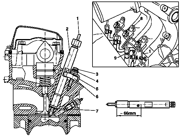
D07.11-0012-06
1 Injection line
2 Nozzle holder
3 Screw
4 Spherical washer
5 Clamping device
6 Clamping claw
7 Sealing ring
8 Bracket
9 Fuel return lines
| Remove/install | ||
1 | Remove electrical connector from needle movement sensor and injection control device | Refer to | |
Removing and connecting distributor pump electrical wires | |||
2 | Remove attached parts at intake manifold | Just slacken charge air hose at intake pipe and remove | |
| |||
3 | Unscrew injection line bracket (8) at intake manifold | | |
| |||
4 | Unscrew injection lines (1) at nozzle holders | | |
5 | Unscrew fuel return lines (9) from nozzle holders | ||
6 | Slacken clamping claw (6) and remove with circuit (5), spherical washer (4) and bolt (3) | Installation: Do not retighten bolts. Replace circuit, spherical washer and bolt. | |
| |||
7 | Withdraw nozzle holder (2) and remove | Use extractor if nozzle holders (2) are stuck | |
| |||
Installation: Replace sealing ring (7) | |||
8 | Install in the reverse order |
Distributor injection pump
Number | Designation | Engine 602.980 | Engine 602.984/ | ||
BA07.13-N-1001-01A | Injection lines to injection nozzle/injection pump | Nm | 18 | 18 | |
BA07.13-N-1006-01A | Bolt, nozzle holder clamping claw to cylinder head | Stage 1 | Nm | 7 | 7 |
Stage 2 | ° | 180 | 180 | ||
BA07.13-N-1007-01A | Bolts, bracket of injection lines to intake manifold | Nm | 10 | 10 | |
Intake manifold, intake manifold preheater
Number | Designation | Engine | Engine | |
BA09.20-N-1002-02B | Bolts, mixing housing to intake manifold | Nm | 9 | 9 |


000 589 68 03 00
355 589 01 63 00
Impact extractor
Box wrench bit
Repair materials
Number | Designation | Order number |
BR00.45-Z-1036-06A | Special grease | A 001 989 42 51 10 |
Referenced documents
- ar0711d550001a Removing and installing nozzle holder
- ar0713d841003a Disconnecting and connecting electric cables on distributor injection pump