
D54.10-1170-08
Shown on model 906 with CODE XM0 (Model refinement) |
1 | Positive line | X4/47 | Circuit 30 battery | |
G1 | On-board electrical system battery |

D01.10-1178-09
Shown on model 906 with transmission 711 |
3 | Propeller shaft | 6 | Diesel particulate filter/front muffler | 9 | Crossmember | ||
4 | Transmission | 7 | Pipe clamp | ||||
5 | Screw | 8 | Exhaust pipe |

10 | Motor |
11 | Ground cable |
12 | Screw |
13 | Engine mount |
14 | Front axle carrier |
15 | Screw |
16 | Screw |
17 | Engine mount |
D01.10-1179-06
Danger | Risk of death caused by vehicle slipping or toppling off of the lifting platform. | Align vehicle between vehicle lift columns and position the four support plates at the vehicle lift support points specified by the vehicle manufacturer. | |
Danger | Risk of explosion caused by fuel igniting, risk of poisoning caused by inhaling and swallowing fuel as well as risk of injury to eyes and skin caused by contactwith fuel. | No fires, sparks, open flames or smoking. Pour fuels into suitable and appropriately marked containers only. | |
Caution | Risk of poisoning from swallowing brake fluid. Risk of injury from skin and eye contact with brake fluid | Only pour brake fluid into suitable and appropriately marked containers. Wear protective clothing and eye protection when handling brake fluid. | |
Topical note | Notes on threaded connections fastened using a tightening angle-based tightening process | ||
Topical note | Notes on self-locking nuts and bolts | ||
Topical note | Brake fluid notes | ||
Topical note | Notes on battery | ||
Topical note | Information on preventing damage to electronic components due to electrostatic discharge | ||
| Remove/install | ||
1 | Disconnect ground line for on-board electrical system battery (G1) | ||
2 | Remove positive line (1) from the battery circuit 30 (X4/47) and expose up to grommet (arrow A) in the battery box | ||
3 | Remove engine hood | ||
4 | Remove front module | ||
5 | Remove engine cover | ||
6 | Jack up vehicle and secure | ||
7 | Disconnect hose and line connections | ||
High pressure expansion hose to power steering pump | |||
Bolt, vehicle speed sensor to transmission housing | |||
Nut, circuit 30 to connection for battery box | |||
Nut, circuit 30 to connection for connecting point | |||
Bolt, refrigerant lines to refrigerant compressor | |||
Steering gear oil | |||
Record plug | |||
8 | Remove 2nd refrigerant compressor and hang to side with lines attached |
| |
9 | Disconnect electrical connectors from transmission (4) | Engine 651.955/956/957 in model 906 with transmission 722.6 | |
10.1 | Remove shift cables from transmission (4) | Engine 651 in model 900 with transmission 711.680 | |
Long-life grease | |||
10.2 | Unhook selector level cable from transmission (4) | Engine 651.955/956/957 in model 906 with transmission 722.6 | |
Transmission 722.6 in model 906 with engine 651.955/956/957 | |||
Transmission 722.9 in model 906 with engine 651.955/956/957 | |||
Long-life grease | |||
11 | Remove propeller shaft (3) at drive flange of transmission (4) and hang up to one side | ||
12 | Loosen pipe clamp (7) and push to the rear on the exhaust pipe (8) | Installation: Clean sealing surfaces and replace gasket. | |
Engine 651.955/956/957 in model 906 | |||
Engine 651.955/956/957 in model 906 | |||
13 | Insert suitable wooden block between the crossmember (9) and the transmission (4) (arrow B) | ||
14 | Remove screw/bolts (5) for rear engine mount | Screw/bolt, rear engine mount to bracket | |
15 | Lower vehicle | ||
16 | Attach mounting plate to the engine (10) | ||
Support plate | |||
17 | Remove screw/bolt (12) and place ground line (11) to one side | ||
18 | Remove screw/bolts (15, 16) for engine mount (13, 17) | Nut/screw/bolt, front engine mount to front axle carrier | |
19 | Lift engine (10) with attached transmission (4) until the engine mounts (13, 17) no longer lie on the front axle carrier (14) | | |
Aid of 2 helpers required. | |||
Installation: Ensure correct seating of the engine mounts (13, 17) on the front axle carrier (14). | |||
20 | Lift engine (10) with attached transmission (4) toward the front out of the engine compartment with the aid of the removal fixture and an engine crane | ||
| 000 588 04 62 00 Removal fixture | ||
| |||
Aid of 2 helpers required. | |||
Installation: When installing a new engine (10): Before inserting the engine (10) in the engine compartment, change the corresponding detachable parts. | |||
Commercially available devices/tools | |||
21 | Remove torque converter from drive plate | Engine 651.955/956/957 in model 906 with transmission 722.686 | |
Engine 651.955/956/957 in model 906 with transmission 722.686 | |||
Engine 651.955/956/957 in model 906 with transmission 722.9 | |||
Transmission 722.9 in model 906 with engine 651.955/956/957Bolt, torque converter to drive plate | |||
Transmission 722.686 in model 906 with engine 651.955/956/957Bolt, torque converter to drive plate | |||
Counterholder | |||
Counterholder | |||
Retaining lock | |||
22 | Attach engine (10) to the assembly stand | When installing a new engine (10) or during continued work for which the engine (10) must be attached to the assembly stand. | |
| 000 588 00 31 00 Assembly stand | ||
| 000 588 08 31 00 Mounting fork adapter | ||
Bolt/nut, differential pressure sensor to bracket | |||
Engine 651 in model 900 | |||
Screw/bolt, engine mount to front engine support | |||
Engine 651 in model 900 with transmission 711.680 | |||
Engine 651 in model 900 with transmission 711.680 | |||
Engine 651.955/956/957 in model 906 with transmission 722.9Bolt, filler pipe to cylinder head | |||
Engine 651.955/956/957 in model 906 with transmission 722.9Bolt, filler pipe to transmission housing | |||
Engine 651.955/956/957 in model 906 with transmission 722.686 | |||
Engine 651.955/956/957 in model 906 with transmission 722.686 | |||
Engine 651.955/956/957 in model 906 with transmission 722.9Bolt, oil line to transmission housing | |||
Engine 651.955/956/957 in model 906 with transmission 722.9Bolt, oil line double clamp to bracket | |||
Engine 651 in model 900 | |||
Engine 651.955/956/957 in model 906 | |||
Record plug | |||
23 | Install in the reverse order | ||
24 | Check power steering oil level and correct if necessary | ||
| |||
Warning | Risk of accident from vehicle starting off by itself when engine running. Risk of injury (bruises and burns) resulting from working on the engine while it is being started or when it is running. | Secure vehicle to prevent it from starting off by itself. Wear closed and snug-fitting work clothes. Do not touch hot or rotating parts. | |
25.1 | Carry out an engine test run | For re-installation of the removed engine (10). | |
25.2 | Perform run-in program after engine replacement | For installation of a new engine (10) or exchange of the engine (10). | |
| |||
26 | Check engine (10) and check all line connection for leaktightness |
Battery |
Number | Designation | Model 906 | Model 900 | ||
BA54.10-N-1001-01G | Nut, circuit 30 to connection for battery box | M8 | Nm | 16 | 16 |
Battery |
Number | Designation | Model 906 | Model 900 | ||
BA54.10-N-1002-01G | Nut, circuit 30 to connection for connecting point | M8 | Nm | 16 | 16 |

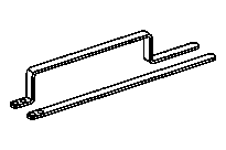


906 589 05 62 00
Support plate
651 589 08 40 00
Counterholder
651 589 02 40 00
Retaining lock
129 589 00 91 00
Record plug
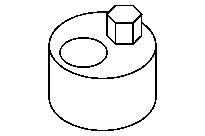
651 589 00 40 00
Counterholder
Referenced documents
- ah0000n000101a Notes on self-locking nuts and bolts
- ah0000p002001a Notes on threaded connections fastened using a tightening angle-based tightening process
- ah4250p000101a Brake fluid notes
- ah5400p000101a Information on preventing damage to electronic components due to electrostatic discharge
- ah5410p000101a Notes on battery
- ah5410p000101a
- ap4600d4611a Check and correct power steering fluid level
- ar0060d1000h Lift/jack up vehicle
- ar0110d240002we Disconnect/connect hose and line connections
- ar0110d240007we Install, disassemble removed engine on assembly stand
- ar0110d240009we Attach, detach engine removal fixture
- ar0110d2405we Remove/install engine cover
- ar0110d240601we Perform run-in program after engine replacement
- ar2660d662601b Detach/attach shift cables at transmission
- ar2719d075001b Disconnect/connect electrical connectors on automatic transmission
- ar2720d010001wf Detach/attach torque converter on driver
- ar2720d010001wg Detach/attach torque converter on driver
- ar2760d010002c Unhook/hook up selector lever Bowden cable on transmission
- ar2760d010002we Unhook/hook up selector lever Bowden cable on transmission
- ar4110d0050h Remove/install propeller shaft
- ar5410d0003sd Disconnect/connect battery ground line
- ar8355d5300we Remove/install refrigerant compressor
- ar8830d1064sd Remove/install front module
- ar8840d3000sd Remove/install engine hood
- as0000z000501a Risk of accident from vehicle starting off by itself when engine running. Risk of injury (bruises and burns) resulting from working on the engine while it is being started or when it is running.
- as0000z001001a Risk of death caused by vehicle slipping or toppling off of the lifting platform.
- as4250z000101a Risk of poisoning from swallowing brake fluid. Risk of injury from skin and eye contact with brake fluid
- as4700z000101a Risk of explosion caused by fuel igniting, risk of poisoning caused by inhaling and swallowing fuel as well as risk of injury to eyes and skin caused by contactwith fuel.
- ws0100n3014b 000 588 04 62 00 Removal fixture
- ws0100n3028b 000 588 00 31 00 Assembly stand for cars
- ws0100p0186b 000 588 08 31 00 Mounting fork adapter