
P54.33-A000-09
Shown on instrument cluster with view of kilometer reading in the multifunction display (30) |
4 | Drive system readiness to drive | 22 | Drive system | |
18 | Fuel level indicator | 23 | Hydrogen alarm | |
19 | Fuel reserve with fuel filler cap position indicator | 30 | Multifunction display | |
21 | Electrical fault |

1 | Fuel cell cover |
P06.00-2049-05
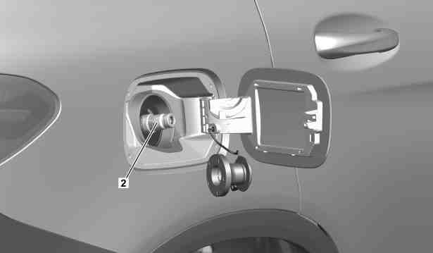
2 | Filler neck |
P06.00-A005-05
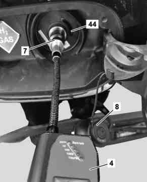
7 | Gas detection unit sensor head |
8 | Cap |
40 | Gas detector |
44 | Infrared sensor |
P47.00-A003-02
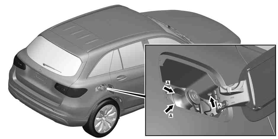
P06.00-A014-09
Pfeil A | High pressure test point |
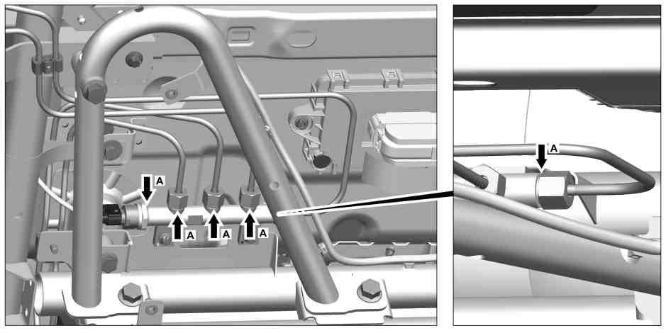
P06.00-A006-09
Pfeil A | High pressure test point |
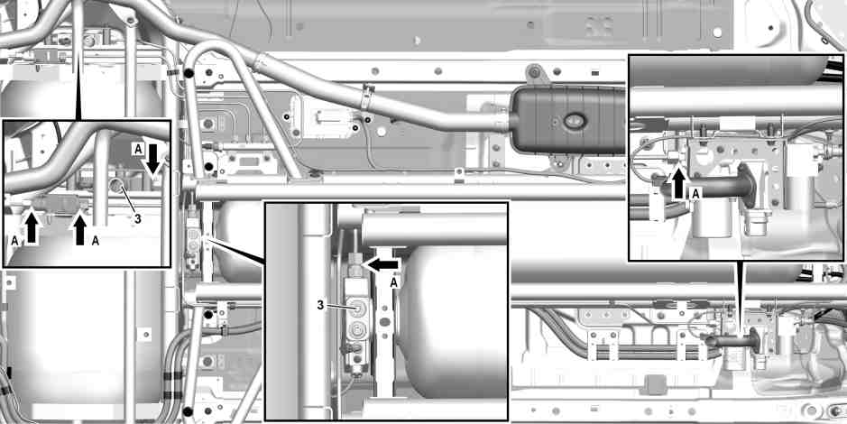
P06.00-A015-09
3 | Manual valve | Pfeil A | High pressure test point |
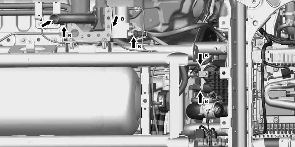
P06.00-A013-09
Pfeil B | Mean pressure test point |
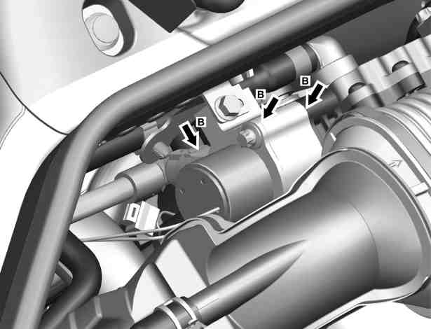
Pfeil B | Mean pressure test point |
P06.00-A011-06
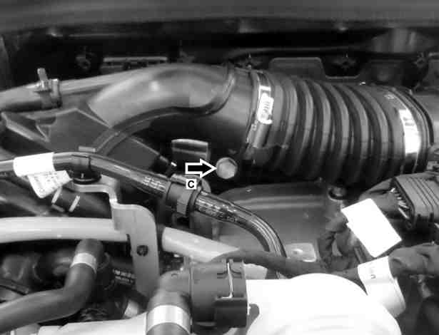
Pfeil C | Mean pressure test point |
P06.00-A010-06

P47.60-A033-09
25 | Rear drain line on gas cylinder in transmission tunnel | 29 | Drain line on gas cylinder above rear axle |

27 | Front drain line on gas cylinder in transmission tunnel |
P47.60-A034-05
Danger | Risk of explosion caused by escaping hydrogen or overheating of the fuel tanks when working on the hydrogen system. Risk of frostbite to body parts caused by escaping gas and by touching component parts carrying gas when emptying fuel tanks. Risk of asphyxiation caused by inhalation of air diluted by hydrogen. Risk of burn injuries by coming into contact with an invisible pale blue hydrogen flame. | ||
Danger | Risk of death when working on component parts and systems with U >= 30 V alternating voltage (AC) or U >= 60 V direct voltage (DC) | Do not touch damaged or defective live component parts and lines or non-insulated electrical connections and lines. | |
Topical note | Notes on fuel cell system | ||
Topical note | General information on handling vehicles with high-voltage on-board electrical system and/or lithium-ion battery and/or gaseous-fuel drive system | ||
| Check | ||
1 | Switch on ignition and check whether the fuel level indicator (18) in the instrument cluster displays > 50 % fill level. | If the fuel level indicator (18) in the instrument cluster displays < 50 % fill level, | |
| |||
refuel vehicle until the fuel level indicator (18) in the instrument cluster displays > 50 % fill level. | |||
After obtaining special order. | |||
2 | Start vehicle and check whether faults relevant to the fuel cell system are present. | The drive system readiness to drive (4) "READY" must be displayed in the instrument cluster. | |
If faults relevant to the fuel cell system are displayed in the multifunction display (30), electrical fault (21), drive system (22) or hydrogen alarm (23) or the fuel reserve with fuel filler cap position indicator (19) is displayed or the drive system readiness to drive (4) does not display "READY", | |||
| |||
determine cause and rectify fault. | |||
After obtaining special order. | |||
3 | Switch off ignition. | ||
4 | Open fuel filler flap. | ||
5 | Remove cap (8) from filler neck (2). | If the cap (8) is missing, | |
| |||
fit new cap (8). | |||
After obtaining special order. | |||
6 | Check cap (8) of filler neck (2) for damage and soiling. | If problems occur, | |
| |||
rectify the problems. | |||
After obtaining special order. | |||
7 | Check filler neck (2) for damage and soiling. | If necessary, use commercially available devices/tools. Explosion-proof flashlight, comparable to AccuLux flashlight MHL 5 EX from Witte + Sutor GmbH. | |
Use safety glasses and protective gloves. | |||
If problems occur, | |||
| |||
rectify the problems. | |||
After obtaining special order. | |||
8 | Check filler neck (2) with gas detection unit (40) for leak tightness. | ||
| 000 588 03 21 00 Gas detector | ||
| |||
Mount gas detection unit sensor head (7) of gas detection unit (40) straight onto filler neck (2). | |||
Use safety glasses and protective gloves. | |||
If the test value on the filler neck (2) itself is < 1 % per volume or < 10000 ppm, | |||
| |||
the filler neck (2) is tight. | |||
If the test value directly on the filler neck (2) itself is > 1 % per volume or > 10000 ppm, | |||
| |||
the filler neck (2) is leaky, replace the filler neck (2). | |||
After obtaining special order. | |||
9 | Check the infrared sensor (44) next to filler neck (2) for damage and soiling. | If problems occur, | |
| |||
rectify the problems. | |||
After obtaining special order. | |||
| Remove | ||
10 | Remove fuel cell cover (1). | ||
11 | Remove underfloor paneling in area of test points (arrows A and B). | ||
| |||
| Check | ||
12 | Check all gas carrying lines, connections and valves in high and mean pressure area for damage and firm seating. | If necessary, use commercially available devices/tools. Explosion-proof flashlight, comparable to AccuLux flashlight MHL 5 EX from Witte + Sutor GmbH. | |
If necessary, use commercially available devices/tools. Swiveling inspection mirror. | |||
Use safety glasses and protective gloves. | |||
If problems occur, | |||
| |||
rectify the problems. | |||
After obtaining special order. | |||
13 | Check high pressure test points (arrows A) using gas detection unit (40) for leak tightness. | ||
| 000 588 03 21 00 Gas detector | ||
If necessary, use commercially available devices/tools. Explosion-proof flashlight, comparable to AccuLux flashlight MHL 5 EX from Witte + Sutor GmbH. | |||
Use safety glasses and protective gloves. | |||
If the value at the test points is < 100 ppm, | |||
| |||
the high pressure test points (arrows A) are tight. | |||
If the value at the test points is > 100 ppm, | |||
| |||
the high pressure test points (arrows A) are leaky. | |||
If the high pressure test points (arrows A) are leaky, | |||
| |||
rectify the problems. | |||
After obtaining special order. | |||
14 | Check mean pressure test points (arrows B and C) using gas detection unit (40) for leak tightness. | ||
| 000 588 03 21 00 Gas detector | ||
Use safety glasses and protective gloves. | |||
If the value at the test points is < 100 ppm, | |||
| |||
the mean pressure test points (arrows B and C) are tight. | |||
If the value at the test points is > 100 ppm, | |||
| |||
the mean pressure test points (arrows B and C) are leaky. | |||
If the mean pressure test points (arrows B and C) are leaky, | |||
| |||
rectify the problems. | |||
After obtaining special order. | |||
15 | Check if the cap is fitted to the drain line on the gas cylinder above the rear axle (29). | If problems occur, | |
| |||
rectify the problems. | |||
After obtaining special order. | |||
16 | Check if the cap is fitted to the rear drain line on the gas cylinder in the transmission tunnel (25). | If problems occur, | |
| |||
rectify the problems. | |||
After obtaining special order. | |||
17 | Check if the cap is fitted to the front drain line on the gas cylinder in the transmission tunnel (27). | If problems occur, | |
| |||
rectify the problems. | |||
After obtaining special order. | |||
| Install | ||
18 | Install underfloor paneling. | ||
| |||
19 | Install fuel cell cover (1). |
Referenced documents
- ah0000p002201rfw Notes on fuel cell system
- ah0000z030001a General information on vehicles with high-voltage on-board electrical system and/or lithium-ion battery and/or gaseous-fuel drive system as well as personal protective equipment
- ar6130p1001rfw Remove/install underbody paneling
- as0000z003001b Risk of explosion caused by escaping hydrogen or overheating of the fuel tanks when working on the hydrogen system. Risk of frostbite to body parts caused by escaping gas and by touching component parts carrying gas when emptying fuel
- as0000z003501a Risk of death when working on component parts and systems with U >= 30 V alternating voltage (AC) or U >= 60 V direct voltage (DC)
- ws4700p0019b 000 588 03 21 00 Gas detector