
P05.20-2360-09
Shown on engine 133 without code A14 (CAMTRONIC) |
01a | Hold-down tool | 04 | Bolts | 3e | Camshaft positioner (inlet) | ||
01b | Hold-down tool | 1 | Cylinder head | 4 | Segment disc | ||
02a | Bracket | 2a | Exhaust camshaft | 4a | Partial segment | ||
02e | Bracket | 2e | Intake camshaft | 5 | Bearing slot | ||
03 | Bearing brackets | 3a | Camshaft positioner (exhaust) |

Schematic diagram |
4 | Segment disc |
4a | Partial segment |
5 | Bearing slot |
6 | Cylinder head cover |
P05.10-2451-06
Warning | Risk of injury. Skin or eye injuries may result when handling hot or glowing objects. | Wear protective gloves, protective clothing and safety glasses, if necessary. | |
Warning | Risk of injury. Moving parts can pinch, crush or, in extreme cases even sever extremities. | No parts of the body or limbs should be within the operating area of mechanical components when moving components. | |
Caution | Risk of injury caused by scraping or cutting body parts on sharp vehicle parts | Always wear protective gloves when working on or near sharp and non-deburred vehicle parts. | |
Caution | Risk of injury to skin and eyes due to handling of engine oil. Risk of poisoning caused by swallowing engine oil | Wear protective gloves, protective clothing and safety glasses. | |
Topical note | Notes on avoiding damage through contamination and foreign objects | ||
| Remove | ||
1 | Lift vehicle with lifting platform. | ||
2 | Remove cylinder head cover (6). |
| |
Engine 270 in model 117, 156, 176, 242, 246.2 | |||
3 | Open service flap on the fender liner of the front right fender. | ||
4 | Turn engine at the center bolt of the crankshaft in the direction of engine rotation to top dead center (TDC) ignition TDC on cylinder 1. | ||
The edge of the section (4a) of the exhaust camshaft (2a) and the bearing slot (5) of the intake camshaft (2e) point upward. | |||
For the following operation steps ensure that the crankshaft is not turned. | |||
Socket wrench bit | |||
Adjust | |||
5 | Remove camshaft positioners (3a, 3e). | ||
6 | Turn exhaust camshaft(2a) and intake camshaft(2e) to basic position. | The edge of the section (4a) of the exhaust camshaft (2a) and the bearing slot (5) of the intake camshaft (2e) must point upward vertically. | |
7 | Install hold-down tools (01a, 01b). | Engine 133 in model 117, 156, 176 | |
Engine 133 in model 117, 156, 176 | |||
Screw in screws (04) until the bearing brackets (03) rest flat on the cylinder head (1). | |||
Holding device | |||
8 | Install the brackets (02a, 02e). | | |
| |||
In order to be able to install the brackets (02a, 02e) on the hold-down tool (01a), it is necessary to turn the exhaust camshaft (2a) and intake camshaft (2e) with the socket wrench socket or with the screw (N 000000 005561) in combination with the disk (A604990 0040). | |||
Holding device | |||
Socket | |||
9 | Install camshaft positioners (3a, 3e) and tighten control valves slightly by hand. | During mounting of the camshaft positioner or the timing chain ensure that the crankshaft does not turn. | |
The final tightening of the control valves first take place after installation of the chain tensioner. | |||
The camshaft positioner (3a, 3e) must still be turned freely to exhaust camshaft (2a) and intake camshaft (2e). | |||
| Install | ||
10 | Install the chain tensioner. |
| |
Engine 270 in model 117, 156, 176, 242, 246.2 | |||
11 | Tighten control valves of the camshaft positioners (3a, 3e) with final tightening. | ||
| Specified engine oils (service) - Overview | ||
Lubricate thread and bolt head contact surface of the control valves. Tighten control valves with torque evenly and without interruption. | |||
12 | Remove brackets (02a, 02e) from the hold-down tool (01a). | Hold-down tools (01a,01b) remain at cylinder head (1). | |
13 | Loosen screws (04) at the hold-down tools (01a, 01b) until the camshafts (2a, 2e) can be turned. | Hold-down tools (01a,01b) remain at cylinder head (1). | |
| Check | ||
14 | Turn engine at the center bolt of the crankshaft in the direction of engine rotation through two revolutions and turn to top dead center (TDC) (ignition TDC) at cylinder 1. | ||
Socket wrench bit | |||
15 | Tighten screws (04) at hold-down tools (01a, 01b) slightly by hand. | ||
16 | Check basic position of the camshafts (2a, 2e); to do this, install the brackets (02a, 02e) on the hold-down tool (01a). | | |
| |||
In order to be able to install the brackets (02a, 02e) on the hold-down tool (01a), it is necessary to turn the exhaust camshaft (2a) and intake camshaft (2e) with the socket wrench socket. | |||
If brackets (02a,02e) cannot be installed, | |||
| |||
Repeat work procedure from operation step 4. | |||
17 | Remove brackets (02a, 02e) and hold-down tools (01a,01b). | ||
18 | Close service flap on the fender liner of the front right fender. | ||
19 | Lower vehicle with vehicle lift. | ||
20 | Install cylinder head cover (6). |
| |
Engine 270 in model 117, 156, 176, 242, 246.2 |

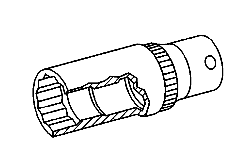

270 589 01 61 00
Holding device
001 589 65 09 00
Socket wrench bit
270 589 01 07 00
Socket
Henviste dokumenter
- ah0000p500001a Oplysninger om forebyggelse af skader på grund af snavs og fremmedlegemer
- ar0060p1000ak
- ar0110p100001mt
- ar0120p5014mt
- ar0120p5014mta
- ar0510p7800mt
- ar0510p7800mta
- ar0520p7201mt
- as0000z000201a Fare for personskade på hud og øjne ved håndtering af varme eller glødende genstande
- as0000z000901a Fare for personskade som følge af klemning af legemsdele, i værste fald fare forafskæring af legemsdele ved indgreb i mekanikken
- as0000z001701a Fare for personskade på grund af snitsår eller hudafskrabninger grundet skarpkantede køretøjsdele
- as1800z000101a Fare for personskade på hud og øjne ved håndtering af motorolie. Fare for forgiftning ved indtagelse af motorolie
- bb0040p022302a