

1 | Coupling flange |
2 | Threaded ring |
3 | Tapered roller bearing (outer) |
4 | Split ring |
5 | Lock |
6 | Shim |
7 | Roller bearing |
8 | Retaining ring |
B35.31-0051-01
B35.31-0050-01
| Remove | ||
1 | Remove the differential with crown gear |
| |
Rear axle 743.439/498 | |||
2 | Remove the screw and lock (5) from the threaded ring of drive pinion (2) | ||
3 | Remove the threaded ring (2) from its housing | | |
| |||
| |||
To not deform the deflector of the flange: | |||
| |||
Rotate the threaded ring (2) a few turns and move the drive pinion away by striking it into the inner side using a mandrel made of a pliable material. | |||
Repeat this until the last thread of the threaded ring (2) is visible. | |||
4 | Remove the drive pinion assembly | | |
Hit the drive pinion end from the inside of the housing with a mandrel of soft material. | |||
5 | Remove the compensation washer from housing (6) | ||
6 | Remove the lock-ring (8) and the outer race of the cylindrical roller bearings (7) | Utilize an appropriate tool. | |
7 | Remove the outer race of the cylindrical rollers bearing (7) | | |
| |||
8 | Disassemble the drive pinion assembly |
| |
Rear axle 743.439/498 | |||
| Install | ||
9 | Assemble the drive pinion assembly |
| |
Rear axle 743.439/498 | |||
10 | Install the external race of cylindrical roller bearings (7) | Install from the inside of the housing. | |
Note the groove parallelism on the external race of cylindrical roller bearings and its housing. | |||
| |||
| |||
11 | Install the lock ring (8) on the outer race of the cylindrical bearing (7) | Install in the same direction of rotation of the drive pinion. | |
12 | Install some shims (6) on the drive pinion housing inside the housing | ||
13 | Position the drive pinion assembly in its housing | | |
| |||
Hit the drive pinion assembly with a plastic hammer until the threaded ring (2) touches the face of the housing. | |||
14 | Install the threaded ring (2) to housing | Remove the two screws which have been used in the installation. | |
Apply a sealing agent on the screwed surface of the ring. | |||
Threaded rings of pinion bearings | |||
Terolan 307/II, Dichtin 51, epple 22 sealant | |||
| |||
| |||
| |||
| Check | ||
15 | Check the basic measurement of the drive pinion depth |
| |
Rear axle 743.4 in Type 688.1/2 | |||
.Pinion (basic depth and thickness or compensation washers) | |||
| |||
| |||
| |||
| |||
16 | Retighten the threaded ring (2) | ||
Apply a sealing agent on the screwed surface of the ring. | |||
Threaded rings of pinion bearings | |||
Terolan 307/II, Dichtin 51, epple 22 sealant | |||
| |||
| |||
| |||
17 | Lock the threaded ring with lock (5) | ||
18 | Install the differential with the crown gear |
| |
Rear axle 743.439/498 |
Differential. ring ear and pinion check values |
Number | Designation | 746.890, 746.891 Rear axles | 746.980/982/983 Rear axle | ||
BE35.31-B-1005-03C | Pinion (basic depth and thickness or compensation washers) | Basic depth | mm | 83,50 | 83,50 |
Thickness of the compensating washers | mm | 0,10, 0,15, 0,20, 0,50, 1,50 | 0,10, 0,15, 0,20, 0,25, 0,50, 1,50 |


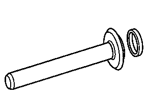

055 589 34 21 00
Adjustment tool
321 589 04 21 00
Adjusting device
345 589 05 15 00
Drift
001 589 53 21 00
Dial gage


384 589 00 07 00
Claw-type wrench
318 589 01 21 02
Adjusting element
000 589 02 13 00
Torque multiplier
730 589 04 15 00
Drift punch

318 589 01 07 00
Slotted nut wrench