Rear axle | 741.914, 742.800/801/807/808, 743.037/038/042/099/251/252/432, 745.982, 746.980 |
plain-flanged | |
Rear axle | 741.930/931, 743.021/022/037/039/044/045/046/057/058/059/060/061/066/076/081/082/083/098/105/107/133/144/148/150/154/305/306/339/340/341/342, 746.580/581/583/585/598/860/861/880/891/980/982 |
plain-flanged | |
Rear axle | 743.107/150, 745.511/518/590/950, 746.560/588/589/590/597/860 |
plain-flanged | |
Rear axle | 743.432 |
plain-flanged | |
Rear axle | 746.87 in model 368, 382, 684 |
plain-flanged | |
Rear axle | 746.990 in model 384 |
plain-flanged | |
Rear axle | 746.991 in model 694, 695 |
plain-flanged | |
Rear axle | 746.994/995/997 in model 958 |
plain-flanged |

1 | Collar nut |
2 | Coupling flange |
3 | Radial shaft sealing ring |
4 | Threaded ring |
5 | Thrust ring |
6 | Tapered roller bearing (outer) |
7 | Split washer |
8 | Spacer disk |
9 | Tapered roller bearing (inner) |
10 | Drive pinion |
11 | Inner race - Cylindrical roller bearings |
12 | Retaining ring |
13 | Lock wrench |
B35.31-0056-06
| Disassemble | ||
1 | Remove the drive pinion assembly from the rear axle |
| |
Rear axle 741.914, 742.800/801/807/808, 745.511/518/950/982; 746.860/880; 746.87 in Type 368, 382, 684; 746.994/995/997 in Type 958 with a plain flange | |||
Each crown gear/drive pinion assembly includes an electrically engraved number at the top of the drive pinion and on the oblique face of the crown gear, indicating matching parts. | |||
2 | Secure the drive pinion assembly in a vise and remove the nut with collar (1) | Retainer wrench | |
3 | Remove the coupling flange (2) or the coupling fork | Puller | |
4 | Remove the threaded ring (4) and the thrust ring (5) | ||
5 | Extract the radial shaft sealing rings (3) of the threaded ring (4) with a suitable mandrel | Drift | |
6 | Extract the tapered roller bearings (6, 9), the split washer (7) and the spacer ring (8) | Puller | |
Puller | |||
Thrust piece | |||
Puller | |||
7 | Remove the lock-ring (12) and the inner race of the cylindrical roller bearings (11) | Puller | |
| Check | ||
8 | Check the component parts for damage and wear | In case of damages or wear to any component part: | |
| |||
Replace the defected parts and lubricate the sliding surfaces. | |||
Hypoid gear oil | |||
| Install | ||
Warning | Risk of injury. Skin or eye injuries may result when handling hot or glowing objects. | Wear protective gloves, protective clothing and safety glasses, if necessary. | |
9 | Heat the inner race of the inner cylindrical roller bearings (9) at approx. 80 °C and install on the drive pinion (10) | Observe the bearing widths: | |
Drift | |||
10 | Install the spacer disk (8) and the outer race of the tapered roller bearings (9, 6) | ||
Warning | Risk of injury. Skin or eye injuries may result when handling hot or glowing objects. | Wear protective gloves, protective clothing and safety glasses, if necessary. | |
11 | Heat the inner race of the inner cylindrical roller bearings (6) at approx. 80 °C and install on the drive pinion (10) | ||
12 | Install the thrust ring (5) | ||
13 | Assemble the new radial shaft sealing rings (3), under pressure into the threaded ring (4) | Axle 743.4, only one radial shaft sealing ring. | |
Observe that the inner radial shaft sealing ring has a simple sealing lip and the outer radial shaft sealing ring has an auxiliary sealing lip. | |||
Apply a sealing agent to the external surface of the radial shaft sealing ring | |||
Terolan 307/II, Dichtin 51, epple 22 sealant | |||
Drift punch | |||
Drift | |||
14 | Install the threaded ring (4) with the radial shaft sealing rings on the drive pinion | Fill with the inner space between the radial shaft sealing rings with lubricating grease. | |
Grease, DB supply specification 6804 - Class 267.0 | |||
15 | Install the coupling flange (2) or the coupling fork at the grooved shaft of the drive pinion (10) | Install the coupling flange (2) until it touches at the thrust ring (5). | |
Fix the collar nut (1) manually. | |||
16 | Fix the coupling flange (2) or the coupling fork in the lock wrench | Fix the lock wrench in the appropriate place and apply the prescribed torque in the collar nut (1). | |
.Mounting nut of pinion coupling flange | |||
Drift punch | |||
Retainer wrench | |||
Warning | Risk of injury. Skin or eye injuries may result when handling hot or glowing objects. | Wear protective gloves, protective clothing and safety glasses, if necessary. | |
17 | Heat the inner race of the cylindrical roller bearings (11) at approx. 80 °C and install at the end of the drive pinion (10) and lock it with the retaining ring (12) | ||
18 | Install the split washer (7) | .Pinion bearings friction torque | |
19 | Install the split washer (7) and check the frictional torque of the drive pinion bearings |
| |
.Thickness of split washers of the pinion bearings - 0.02 mm increments | |||
Tester | |||
Torque meter | |||
20 | Lock the collar nut (1) by punching its collar on the drive pinion slot | ||
21 | Install the drive pinion on the rear axle |
| |
Rear axle 741.914; 742.800/801/807/808; 745.511/518/950; 745.982; 746.860/880; 746.87 in Type 368, 382, 684 with a plain flange |


000 589 45 33 00
Puller
344 589 00 34 00
Thrust piece
001 589 49 21 00
Torque meter
745 589 00 15 00
Drift punch


354 589 01 21 00
Tester
321 589 04 35 00
Puller
035 589 01 33 00
Puller
717 589 00 31 00
Retainer wrench


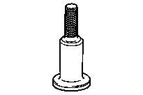
310 589 00 15 00
Drift
370 589 01 15 00
Drift
312 589 05 15 00
Drift
Repair materials |
Number | Designation | Order number |
BR00.45-Z-1018-01A | Terolan 307/II, Dichtin 51, epple 22 sealant | Use corresponding commercially available repair materials. |
BR00.45-Z-1023-06A | Hypoid gear oil | A 000 989 28 03 |
BR00.45-Z-1107-06A | Grease, DB supply specification 6804 - Class 267.0 | Use corresponding commercially available repair materials. |