


711 589 01 37 00
Drift
Set of assembly clamps
Drift
Sleeve
198 589 03 39 00
711 589 07 15 00
716 589 02 33 00
For installing the synchronizer units the respective seat on the main shaft and contact surfaces of the synchronizer units must be grease-free.
A workshop press is required for pressing on the synchronizer units. The required press force is approx. 3 t.
Oil friction rings, cone rings, synchronizer rings and needle bearings lightly with automatic transmission fluid before installing.

1 Attach main shaft, drive side upwards, with the fixed gear of 3rd gear (31) to the workshop press mount.
2 Install needle bearing of 6th gear (20).
3 Install clutch body (22), synchronizer ring (23) and synchronizer unit of 5th/6th gear (24).
The inscription on the synchronizer unit of 5th/6th gear (24) must point towards the drive side. The drivers of the synchronizer ring (23) must engage in the grooves of the synchronizer unit of 5th/6th gear (24).
4 Press synchronizer unit for 5th/6th gear (24), synchronizer ring (23), clutch body (22) and
idler gear of 6th gear (21) on as far as the end stop on the mainshaft using drift
(198 589 03 39 00) .
D26.50-1259-03

D26.50-1260-01
5 Determine thickness of the circlip (27):
- Insert circlip (27) with a thickness of 1.70 mm as a test ring into the security groove and press until it abuts downwards in the direction of the synchronizer unit of 5th/6th gear (24).
- Measure the gap between the test ring and the upper edge of the security groove using a feeler gauge.
- Thickness of required circlip (27) = measured value + 1.70 mm (test ring).
- Remove test ring.
Circlips (27) are available with a thickness of 1.70 up to 2.05 mm and a graduation of 0.05 mm.
6 Install circlip (27).

7 Attach main shaft, output side upwards, with the fixed gear of 4th gear (32) to the workshop press mount.
8 Install needle bearing of 2nd gear (18).
9 Install friction ring (16) and cone ring (15) on idler gear of 2nd gear (17).
The cam of the friction ring (16) must point towards the output side. The cams of the cone ring (15) must engage in the cutouts of the idler gear of 2nd gear (17).
10 Install synchronizer ring (14) on idler gear of 2nd gear (17).
The toothing on the synchronizer ring (14) must point towards the idler gear of 2nd gear (17). The cams of the friction ring (16) must engage in the cutouts of the synchronizer ring (14).
11 Attach synchronizer unit of 1st/2nd gear (13) to synchronizer ring (14).
The marking groove on the collar of the sliding sleeve of the synchronizer unit of 1st/2nd gear (13) must point towards the idler gear of 2nd gear (17). The cams of the synchronizer ring (14) must engage in the cutouts of the synchronizer unit of 1st/2nd gear (13).
D26.50-1257-03

D26.50-1238-01
12 Secure synchronizer unit of 1st/2nd gear (13) and idler gear of 2nd gear (17) with assembly clamp (56) and press on as far as the end stop using sleeve.
13 Remove assembly clamp (56).

D26.50-1261-01
14 Determine thickness of the circlip (12):
- Insert circlip (12) with a thickness of 2.40 mm as test ring in the security groove and press downwards until it abuts in the direction of the synchronizer unit of 1st/2nd gear (13).
- Measure the gap between the test ring and the upper edge of the security groove using a feeler gauge.
- Thickness of required circlip (12) =
measured value + 2.40 mm (test ring).
- Remove test ring.
Circlips (12) are available with a thickness of 2.40 up to 2.80 mm and a graduation of 0.05 mm.
15 Install circlip (12).

D26.50-1262-01
16 Install synchronizer ring (11), cone ring (10) and friction ring (9).
The toothing of the synchronizer ring (11) and cams of the cone ring (10) must point towards the output side. The cams of the friction ring (9) must engage in the cutouts of the synchronizer ring (11).

17 Install needle bearing of 1st gear (8).
18 Slide on idler gear of 1st gear (7) and attach thrust plate (6).
The cams of the cone ring on the synchronizer unit of 1st/2nd gear (13) must engage in the cutouts of the idler gear of 1st gear (7).
19 Press on bearing bushing of reverse gear (5) as far as the end stop using drift (711 589 07 15 00).
20 Install needle bearing of reverse gear (4) and idler gear of reverse gear (3).
The collar of the idler gear of reverse gear (3) must point towards the output side.
21 Install synchronizer ring (2) with toothing towards the idler gear of reverse gear (3).
D26.50-1263-03

D26.50-1239-01
22 Secure synchronizer unit of reverse gear (1) using assembly clamp (55) and press on as far as the end stop using drift (711 589 07 15 00).
The marking groove on the collar of the sliding sleeve of the synchronizer unit of reverse gear (1) must point towards the idler gear of reverse gear. The drivers of the synchronizer ring (2) must engage in the cutouts of the synchronizer unit of reverse gear (1).
23 Remove assembly clamp (55).
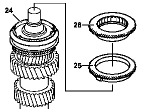
D26.50-1272-01
24 Remove main shaft from the workshop press mount.
25 Attach synchronizer ring (25) with clutch body (26) on drive side to the synchronizer unit of
5th/6th gear (24) and secure to prevent it from falling down.
The drivers of the synchronizer ring (25) must engage in the grooves of the synchronizer unit of 5th/6th gear (24).