Modification notes |
10.9.13 | "Remove oil restrictor (69) from main shaft (22)" added. | Operation step 8 | AR26.50-W-0004H |
10.9.13 | "Attach assembly device (73) to transmission (72) and move to upright position" added. | Operation step 10 | AR26.10-W-0001-01HE |
10.9.13 | "Detach assembly device (73) from transmission housing center section (19) and set down horizontally" added. | Step 28 |

W26.10-1067-09
1 | Countershaft bearing cap | 12 | Tapered roller bearing outer race | 20 | Tapered roller bearing outer race | ||
2 | Tapered roller bearing outer race | 13 | Reverse gear | 21 | Shift unit | ||
3 | Drive shaft bearing cap | 14 | Range group | 22 | Main shaft | ||
4 | Tapered roller bearing outer race | 15 | Slide hammer puller | 23 | Synchronizer cone with synchronizer and annular spring | ||
5 | O-ring | 16 | Threaded insert | 24 | Drive shaft | ||
6 | Retaining ring | 17 | Reverse idler shaft | 25 | Shift | ||
7 | Front section of transmission housing | 18 | Bearing bolt for shift unit | B17 | Speed sensor | ||
11 | Countershaft | 19 | Center section of transmission housing |

11 | Countershaft |
13 | Reverse gear |
19 | Center section of transmission housing |
21 | Shift unit |
22 | Main shaft |
23 | Synchronizer cone with synchronizer and annular spring |
24 | Drive shaft |
26 | Holding device |
30 | Oil pipe |
W26.10-1112-06

7 | Front section of transmission housing |
32 | Pulling device |
W26.40-1018-01

22 | Main shaft |
69 | Oil restrictor |
W26.50-1217-06

72 | Transmission |
73 | Assembly device |
W26.50-1216-12
| Disassemble | ||
1 | Remove clutch operating system | ||
2 | Remove shift mechanism (25) | Vehicles with code GS3 ("Hydraulic" gearshift) | |
Vehicles with code GS1 ("Manual" gearshift) | |||
3 | Detach electrical line and compressed air lines at connectors and at brackets | ||
4 | Remove reverse gear switch | ||
5 | Remove countershaft rpm sensor | ||
6 | Remove road speed sensor (B17) | ||
7 | Remove range group (14) | ||
8 | Remove oil restrictor (69) from main shaft (22) | Only if fitted. | |
9 | Remove reverse idler shaft (17) using threaded insert (16) and impact extractor (15) | ||
| Threaded insert for removing reverse idler shaft | ||
Impact extractor | |||
10 | Attach assembly device (73) to transmission (72) and move to upright position | ||
Assembly device | |||
11 | Remove countershaft bearing cap (1) | ||
12 | Remove drive shaft bearing cap (3) | ||
13 | Remove O-ring (5) and retaining ring (6) from oil pipe (30) | If necessary, lift up the oil pipe (30) from below. | |
14 | Remove bearing bolt for shift unit (18) | Extraction claw | |
Impact extractor | |||
15 | Remove bolts securing transmission housing front section (7) to transmission housing center section (19) | ||
16 | Remove front section of transmission housing (7) | Do not damage sealing surfaces. | |
Hand pump | |||
Hydraulic hose (complete) | |||
Hydraulic cylinder | |||
Adapter | |||
Adapter | |||
Puller | |||
Retaining device | |||
17 | Remove tapered roller bearing outer races (2, 4) from transmission housing front part (7) | Use a suitable drift. | |
18 | Remove drive shaft (24) | ||
19 | Remove synchronizer cone with synchronizer ring and annular spring (23) | ||
20 | Fix shift unit (21) in position on both sides using cable ties (arrow) | ||
21 | Install holding device (26) through the oil hole on main shaft (22) and raise main shaft (22) approx. 15 mm | Retainer device | |
22 | Push reverse idler gear (13) to side until tapered roller bearing of countershaft (11) is exposed | ||
23 | Tilt countershaft (11) to one side and lift out | If necessary, lift the main shaft (22) further | |
24 | Lift out main shaft (22) together with shift unit (21) and oil pipe (30) | ||
25 | Clamp main shaft (22) together with shift unit (21) and oil pipe (30) on sun gear in clamping device | Clamping device | |
26 | Remove oil pipe (30) between shift unit (21) and main shaft (22) | ||
27 | Remove reverse idler gear (13) from transmission housing center section (19) | ||
28 | Detach assembly device (73) from transmission housing center section (19) and set down horizontally | ||
29 | Remove tapered roller bearing outer races (12, 20) from the transmission housing center part (19) | Use a suitable drift. | |
30 | Disassemble main shaft (22) with shift unit (21) | ||
31 | Disassemble drive shaft (24) | ||
32 | Disassemble countershaft (11) |


315 589 02 31 00
Clamping device
652 589 00 33 23
Hydraulic hose (complete)
652 589 00 33 21
Hand pump
355 589 01 63 00
Impact extractor

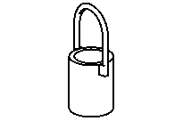


715 589 08 31 00
Assembly device
715 589 05 31 00
Retaining device
715 589 11 34 00
Adapter
715 589 08 33 00
Puller


715 589 04 31 00
Retainer device
715 589 12 34 00
Adapter
715 589 06 33 00
Extraction claw
715 589 15 34 00
Hydraulic cylinder