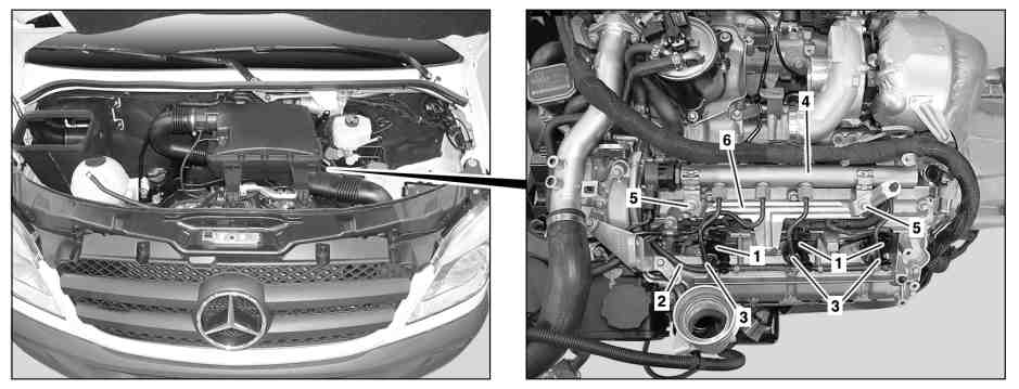
D07.16-1319-08
Shown on engine 642.992, left cylinder head |
1 | Electrical connectors | 3 | Injection lines | 5 | Screw | ||
2 | Leak oil line | 4 | Rail | 6 | Bracket |

D07.16-1318-08
Shown on engine 642.992, right cylinder head |
7 | Electrical connectors | 9 | Injection lines | 11 | Screw | ||
8 | Leak oil line | 10 | Rail | 12 | Bracket |
Danger | Risk of explosion caused by fuel igniting. Risk of injury to skin and eyes caused by fuel spraying out at high pressure | Keep all ignition sources out of hazard area. | |
Danger | Risk of explosion caused by fuel igniting, risk of poisoning caused by inhaling and swallowing fuel as well as risk of injury to eyes and skin caused by contactwith fuel. | No fires, sparks, open flames or smoking. Pour fuels into suitable and appropriately marked containers only. | |
Notes about Common-Rail components | |||
Remove/install injection lines (3) of the left cylinder head | |||
1 | Remove cover from the left cylinder head cover | ||
Installation: Reinstall cover only after the leak test. | |||
2 | Disconnect electrical connectors (1) from the injectors | ||
3 | Unclip leak oil line (2) from the injectors and place to one side | ||
Do not remove leak oil line (2). | |||
4.1 | Remove screw/bolts (5) and bracket (6) | Engine 642.896/898 | |
Screw/bolt, rail to cylinder head | |||
4.2 | Remove screws (5) and place bracket (6) on the cylinder head | Engine 642.992/993 | |
Screw/bolt, rail to cylinder head | |||
5 | Unscrew injection lines (3) from the rail (4) and injectors | Installation: For stress-free assembly, first screw injection lines (3) finger-tight onto the rail (4) and then tighten injection lines (3) with tightening torque. | |
Union nut, pressure line to rail | |||
Union nut, pressure line to injector | |||
Open wrench insert, (18 mm) | |||
Box wrench bit | |||
6 | Remove injection lines (3) | | |
Installation: Check sealing cone of the injection lines (3) for damage; replace injection lines (3) if necessary. | |||
Record plug | |||
Remove/install injection lines (9) of the right cylinder head | |||
7 | Remove cover from the right cylinder head cover | ||
Installation: Reinstall cover only after the leak test. | |||
8 | Disconnect electrical connectors (7) from the injectors | ||
9 | Unclip leak oil line (8) from the injectors and place to one side | ||
Do not remove leak oil line (8). | |||
10 | Remove screws (11) and release bracket (12) | Screw/bolt, rail to cylinder head | |
11 | Unscrew injection lines (9) from the rail (10) and injectors | Installation: For stress-free assembly, first screw injection lines (9) finger-tight onto the rail (10) and then tighten injection lines (9) with tightening torque. | |
Union nut, pressure line to rail | |||
Union nut, pressure line to injector | |||
Open wrench insert, (18 mm) | |||
Box wrench bit | |||
12 | Remove injection lines (9) | | |
| |||
Installation: Check sealing cone of the injection lines (9) for damage; replace injection lines (9) if necessary. | |||
Record plug | |||
13 | Install in the reverse order | ||
Warning | Risk of accident from vehicle starting off by itself when engine running. Risk of injury (bruises and burns) resulting from working on the engine while it is being started or when it is running. | Secure vehicle to prevent it from starting off by itself. Wear closed and snug-fitting work clothes. Do not touch hot or rotating parts. | |
14 | Perform engine test run and check leak tightness in the area of the injection lines (3 and 9) |


000 589 30 01 00
Open wrench insert, (18 mm)
000 589 68 03 00
Box wrench bit
129 589 00 91 00
Record plug